1.4.4.
Crystal Oscillator
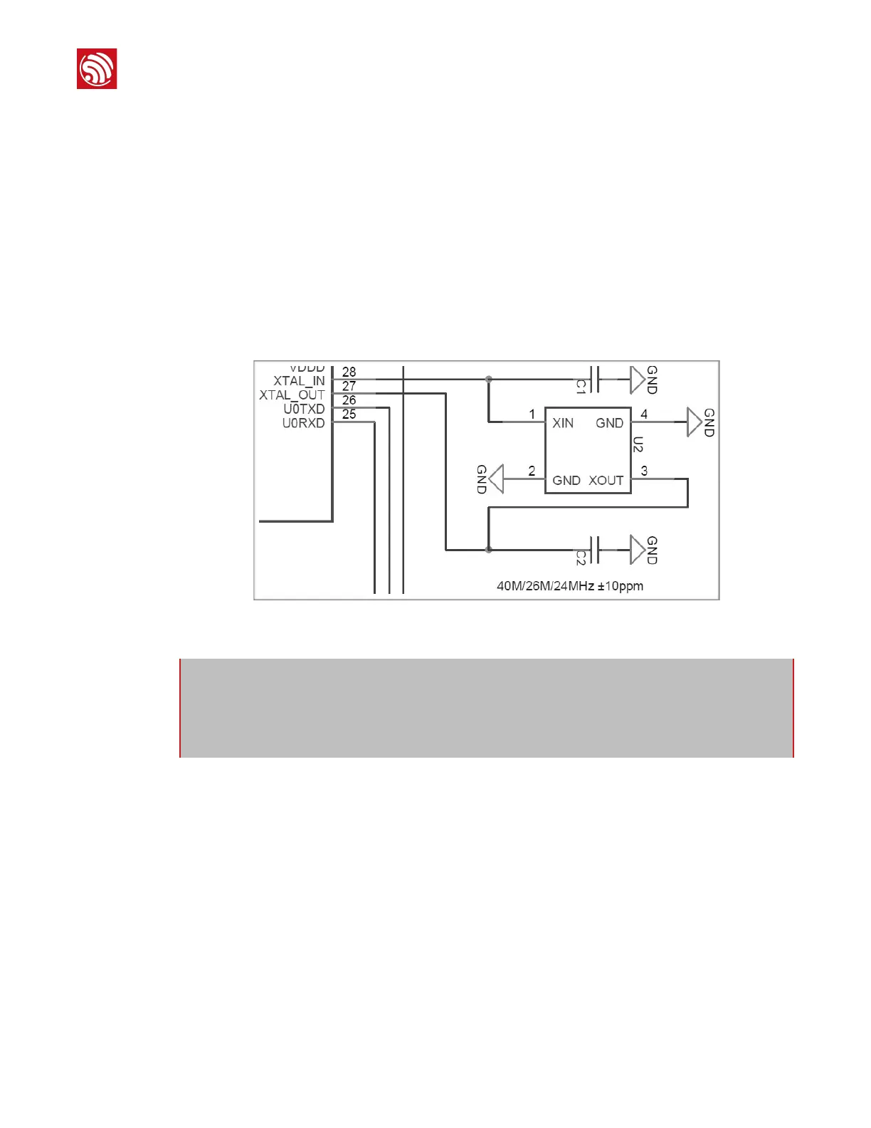
40 MHz, 26 MHz and 24 MHz crystal oscillators are supported. The accuracy of crystal
oscillators should be ± 10 PPM, and the operating temperature range should be between -20°C
and 85°C.
Select the corresponding crystal oscillator type in ESP Flash tool. In circuit design, capacitors C1
and C2 which are connected to the earth are added to the input and output terminals of the
crystal oscillator respectively. The values of the two capacitors can be flexible, ranging from 6
pF to 22 pF. However, the specific capacitive values of C1 and C2 depend on further testing
and adjustment on the overall performance of the whole circuit. Normally, the capacitive
values of C1 and C2 are within 10 pF if the crystal oscillator frequency is 26 MHz, while the
values of C1 and C2 are 10 pF < C1, C2 < 22 pF if the crystal oscillator frequency is 40 MHz.
Figure 1-7: ESP8266EX Crystal Oscillator
1.4.5.
RF
The output impedance of RF pin (Pin2) is 50 Ω. Normally, when the antenna impedance
approaches 50 Ω, antenna matching is not necessary. However, some low-price antennas
commercially available in the market do not feature 50 Ω impedance. Besides, the impedance
in 2.4 G to 2.5 G frequency band is rather scattered. Therefore, π-type matching network-type
matching network is essential in circuit design to facilitate antenna matching.
⚠Notice:
Defects in the craftsmanship of the crystal oscillators (for example, high frequency deviation and
unstable working temperature) may lead to the malfunction of ESP8266EX, resulting in the
decrease of overall performance.
 Loading...