1.4.
Schematics
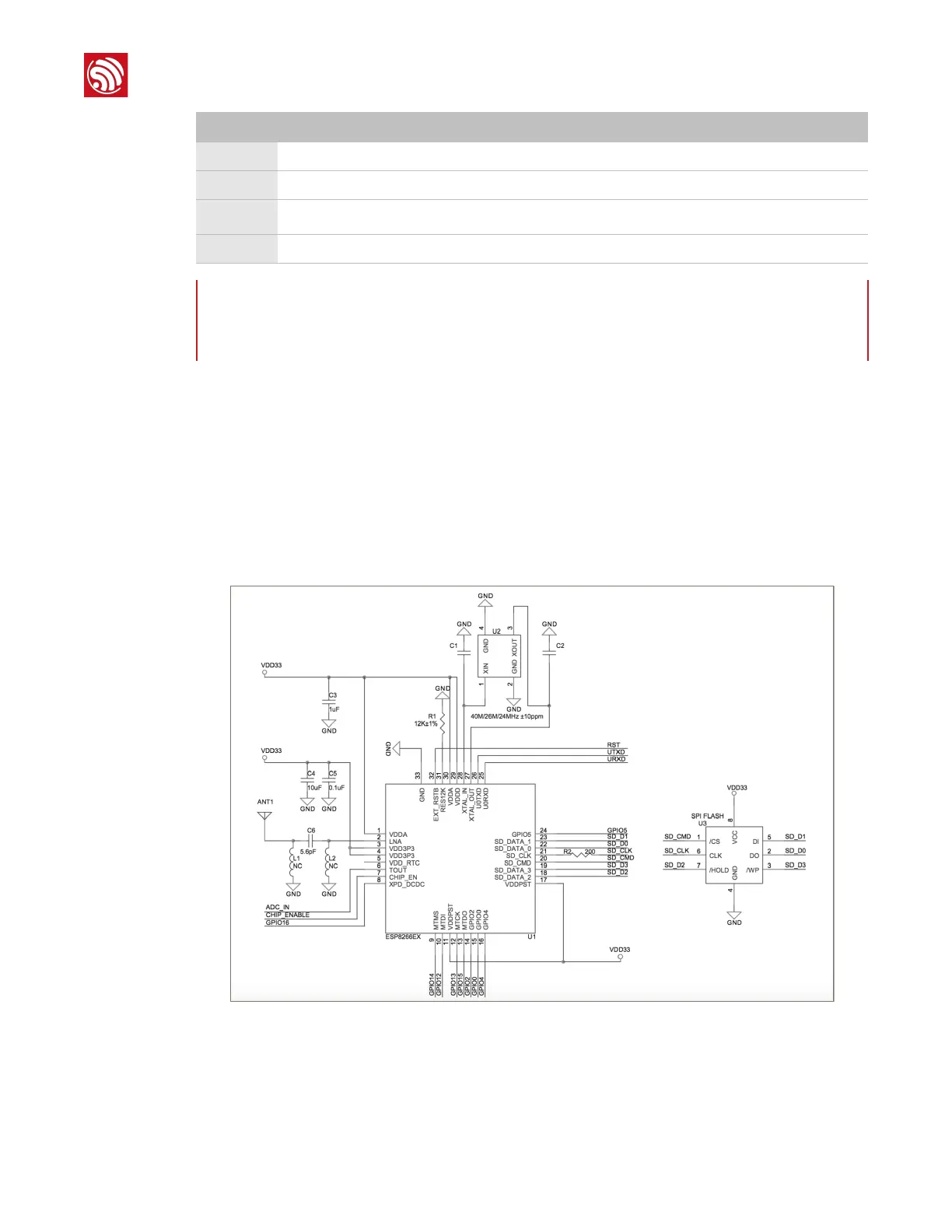
The highly integrated design of ESP8266EX tremendously reduce the number of components
required. Beside ESP8266EX, less than 10 resistors and capacitors, 1 crystal oscillator and 1 SPI
flash are needed to make a complete module with wireless communication capability. The
following is a detailed description on ESP8266EX schematics and layout design to ensure
optimum functionality.
The complete circuit diagram of ESP8266EX is illustrated in Figure 1-3.
Figure 1-3: ESP8266EX Schematics
ESP8266EX schematics design includes six aspects:
•
Power supply
•
Power-on sequence and reset
Note:
GPIO2, GPIO0 and MTDO can be configured to a 3-bit strapping register that determines the
booting mode and the SDIO timing mode.
 Loading...