Take the mainboard of PAD or TV BOX as an example, following aspects shall be noted in
system design.
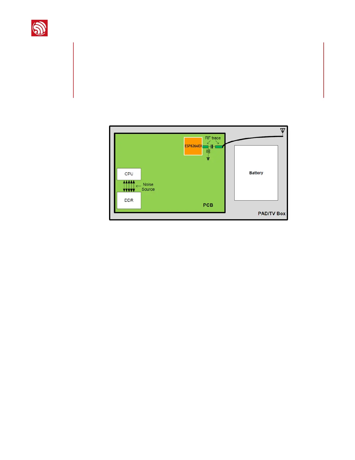
Figure 1-14: PCB Plane Layout
As shown in Figure 1-14, ESP8266EX is on the edge of PCB and away from CPU and DDR
which are the noise source interfering with Wi-Fi frequency in the air. The distance between
chipset and CPU + DDR decrease the interference and reduces the coupling noise.
It is suggested to add a 200 Ω series resistor to the six signal lines when ESP8266EX
communicates with CPU via SDIO to decrease the drive current and interference, and also
eliminate the sequence problem caused by the inconsistent length of SDIO lines.
PCB on-board antenna is not recommended as it receives larger interference and coupling
noise which impact RF performance. It is suggested to use external antenna which is directed
away from PCB board via cable and weaken the high frequency interference to Wi-Fi.
The high frequency signal lines between CPU and MEM should be noted. The line layout should
comply with the high frequency signal regulations (refer to the relative documents about DDR
lines layout). CLK and data/addr lines should be lined underground.
The GND of Wi-Fi circuit and other high power devices should be separated and connected
through wires if there are electric machines in system design.
Antenna should keep away from noise source of high frequency, such as LCD, HDMI, Camera
Sensor, USB, etc.
1.5.3.
Typical Layout Problems And Solutions
•
Q: The current ripple is not large, but the TX performance of RF is rather poor.
Notes:
1. CHIP_PD, as an enable pin, should be connected to a GPIO of Host CPU.
2.
Dual SPI Flash (DIO/DOUT): Remove R12, R13, R15 and keep R10, R9.
3.
Quad SPI Flash (QIO/QOUT): Remove R9, R10 and keep R13, R12, R15.
a.
1 bit SDIO: No need to connect SD_D2 and SD_D3 to Host.
b.
SPI: SD_D3 is reused as SPI_CS and no need to be connected to Host.
 Loading...