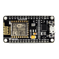
Figure 1-8: ESP8266EX RF
1.4.6.
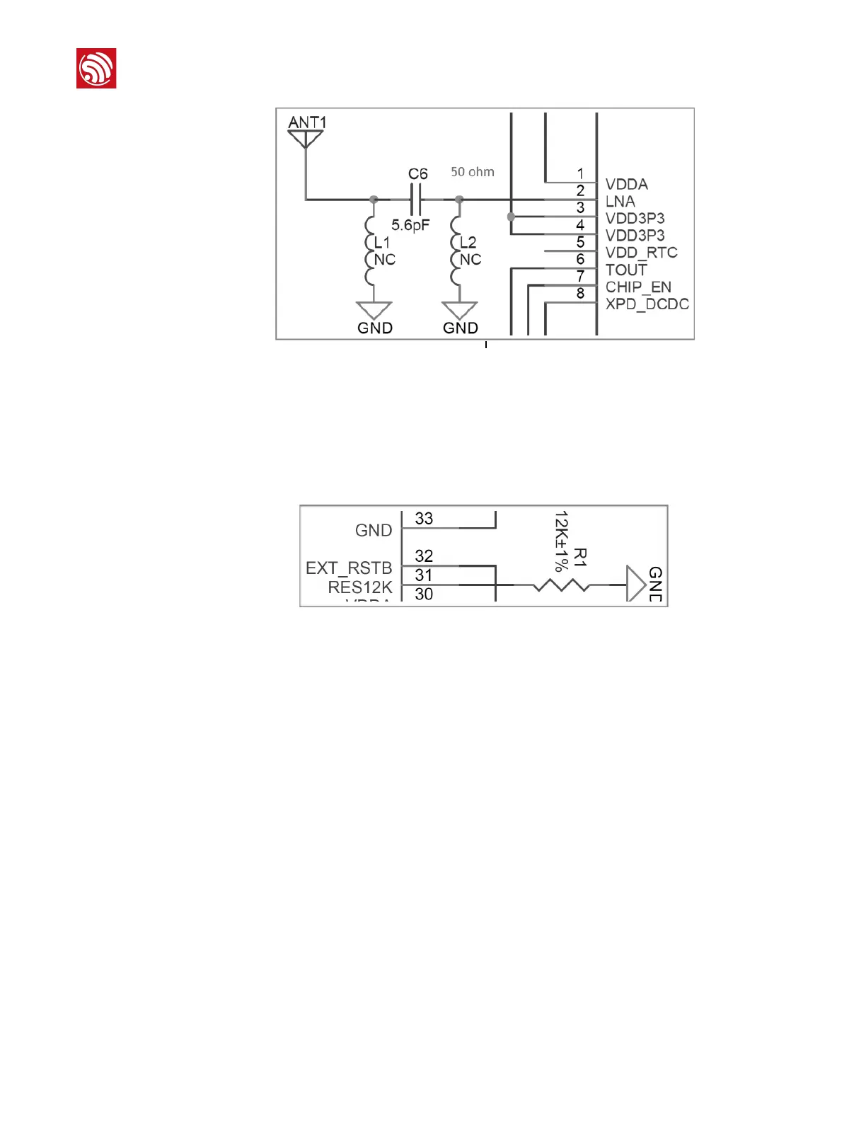
External Resistor 12K
An external ground resistor should be connected o ERS12K pin (Pin31). The ground resistor
requires high accuracy when controlling the bias current. An accuracy of 12K ± 1% is
recommended.
Figure 1-9: ESP8266EX External Resistor
1.5.
Layout Design
Two layout designs are introduced in this section:
•
Standalone ESP8266EX module
•
ESP8266EX module as salve device
1.5.1.
Standalone ESP8266EX Module
Layout Design
The printed circuit board has four layers:
•
The first layer is the TOP layer for signal lines and components.
•
The second layer is the GND layer, no signal lines are laid to ensure an entire plain GND
plane.
•
The third layer is the POWER layer where only power lines can be placed. It is acceptable to
place some signal lines under unavoidable circumstances.
 Loading...