•
The forth lay is the BOTTOM layer. Only signal lines can be laid. It is not recommended to
place components on this layer.
Power Supply Design
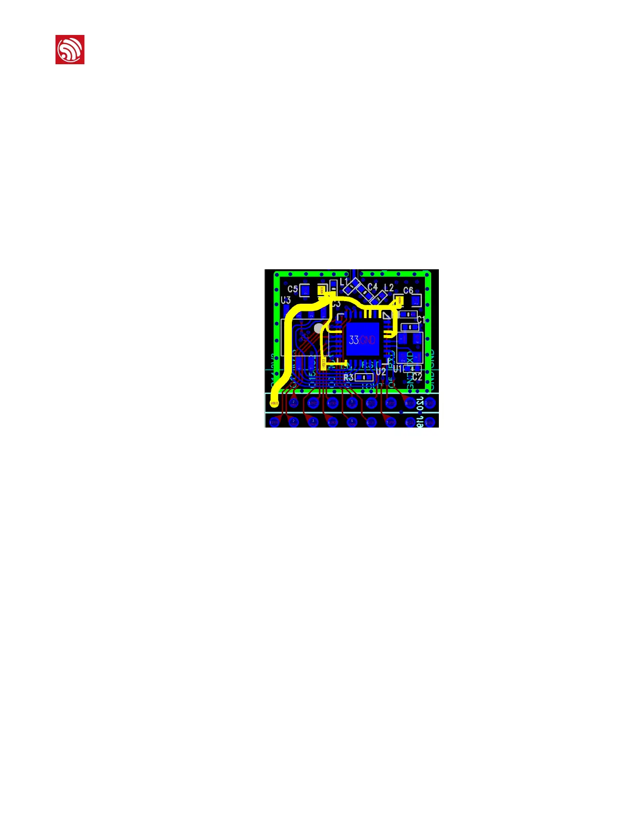
3.3 V power lines are highlighted in Figure 1-10. The total width of the power line should be
larger than 15 mil.
Before the power line reaches the analog power-supply pins (including Pin 1, 3, 4, 28, 29) of
ESP8266EX, a 10 μF 0603 or 0603 capacitor (C6 in Figure 10) needs to be added. The
capacitor should be placed adjacent to the analog power-supply pins of the chipset.
Power lines should be placed on the third layer. When the power lines reached the pins of the
chipset, VIAs are needed so that the power lines can go through the layers to connect the pins
of the chipset on the TOP layer. The diameter of the VIA holes should exceed the width of
power lines and the drilling should be a little bit larger than the radius of VIA.
Figure 1-10: ESP8266EX PCB layout
Crystal Oscillator Design
Crystal oscillator should be placed as close to the XTAL pins as possible (without the traces
being too long). It is good practice to add high density ground vias around the clock trace for
great insulation.
There should be no vias on the input and output traces, which means the traces cannot cross
layers. In addition, the input and output traces should not be routed over one another, not
even on different layers.
Place the input and output bypass capacitors on the near left or right side of the chip. Do not
place them on the traces.
Do not route high-frequency digital signal lines in the four-layer board. It is best not to route
any signal line under the crystal oscillator. The larger the copper area on the top layer is, the
better. As crystal oscillator is a sensitive component, do not place magnetic components such
as high current inductance nearby.
 Loading...