1.6.
Application
1.6.1.
Wi-Fi Smart Hardware Converted from UART Serial Ports
The two UART interfaces are defined as Table 1-3.
AT+ instructions relevant documentations are provided with software.
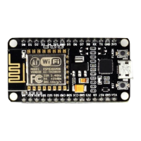
Application example: ESP8266EX development board (see Chapter 2).
1.6.2.
Sensor
ESP8266EX can be used in sensor products, using the I2C interface. The I2C works in the
master mode and can connect to multiple sensors. The slave devices is identified through
addressing mode (each slave device has a unique address identity).
The sensor products send the real-time data to ESP8266EX via I2C interface, and ESP8266EX
uploads the data to server wirelessly. Users can acquire information from server through
applications when the mobile phone connects to internet.
1.6.3.
Smart Light
ESP8266EX can be used to develop smart home products, such as smart light using PWM and
infrared interfaces. Three PWM interfaces controls red, blue, and green LEDs respectively. The
minimal PWM duty ratio is 1/2
14
. In addition, infrared interfaces allows specific control on LEDs,
such as rest, power on/off, color switch, etc.
1.6.4.
Smart Plug
ESP8266EX can be used for developing smart plug products. The GPIOs control the power
switch through the high/low levels switch and connection/disconnection of relay. Such an
application comprises of three modules: 220 V to 3.3 V power conversion module, ESP8266EX
Wi-Fi module and relay control module.
 Loading...