Installation
Table Chapter 3-1: Annunciator IRC-3 & FCC Terminal
Connections
TB1- Function
1 (+) External Key switch-open switch disables
panel, requiring password (not supervised)
2 (-) External Key switch-open switch disables
panel, requiring password (not supervised)
3 RS-485, Ch 0 (+)
4 RS-485, Ch 0 (-)
5 RS-485, Ch 1 (+)
6 RS-485, Ch 1 (-)
7 (+) 24 VDC
8 24 VDC Common
9 Earth Ground
RJ-11
WHT
RS-232, Common
RS-232 - Common on printer
(To common on PC serial port
when downloading)
RJ-11
RED
RS-232, T
X
Out
RS-232 - Rx In on printer
(To data Rx on PC serial port when
downloading)
RJ-11
YEL
RS-232, Rx In
RS-232 - Tx Out on printer
(To data Tx on PC serial port when
downloading)
Note: For Style 4 (Class B) wiring, use only RS-485 Channel 0. For
Style 7 (Class A) wiring, use both RS-485 channels.
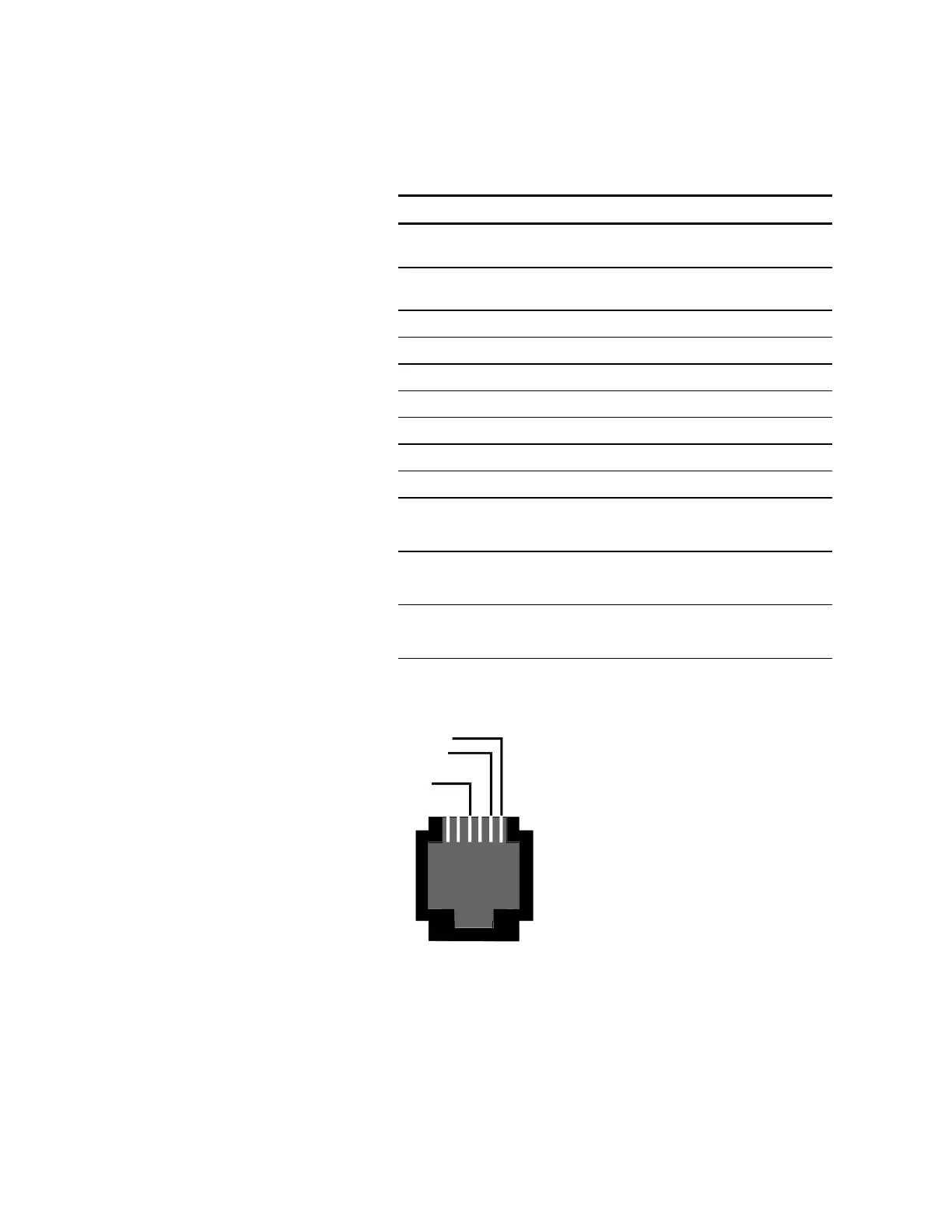
(RJ-11.CDR)
hite (com)
Yell ow (Rx )
Red (Tx)
NC
Top View, RJ1
on LSRA-232
NC
Figure Chapter 3-3: RJ-11 Wiring Color Code
EOL Resistor Installation
UL listed 100 Ohm EOL resistors ( P/N 260071 or EOL-100) are used
to terminate each RS-485 circuit. The RS-485 terminating EOL
LSRA Installation, Operation, Maintenance, and Configuration Manual 3.5