Installation
LSRA(-C)
1 2 34567 8 9
(REAR VIEW)
TB1
LSRA(-C)
1 2 34567 8 9
(REAR VIEW)
TB1
TB1
CM1N
1
2
3
4
5
6
7
8
9
10
TB1
CM2N
1
2
3
4
5
6
7
8
9
10
TB1
CM2N
1
2
3
4
5
6
7
8
9
10
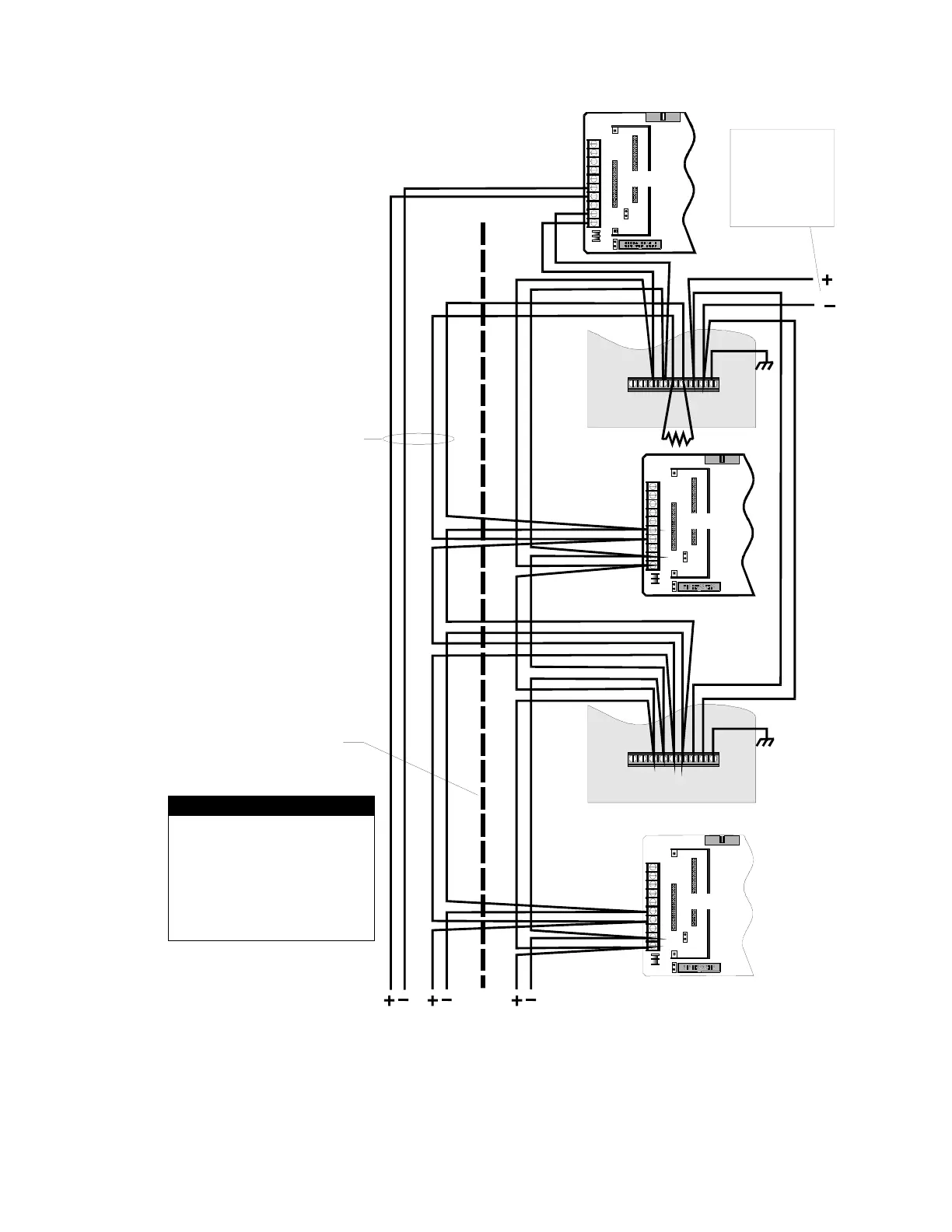
To Balance of IRC-3 Network
From Last Device
n N
w
k
Wiring required for
Class A circuits only
Provide physical separation
between two wire bundles to
ensure network survivability
[XMDN-012.CDR]
1
NOTES
ALL WIRING SUPERVISED AND
POWER LIMITED.
2. ROUTE POWER LIMITED WIRING
SEPARATE AND AWAY FROM NON-
POWER LIMITED WIRING.
3. ALL WIRING 18 AWG, TWISTED.
4. UL listed 100 OHM EOL RESISTOR
(P/N 260071or EOL-100) REQUIRED
AT PHYSICAL END OF RS-485 WIRING.
24 VDC FROM:
APS-4B(-220)
APS-8B
PS4B(-220)
PS8B
SIGA-APS
Figure Chapter 3-4: IRC-3 Class A and Class B RS-485 Data Line Wiring
LSRA Installation, Operation, Maintenance, and Configuration Manual 3.7