Installation
LSRA(-C)
1 2 345678 9
(REAR VIEW)
TB1
LSRA(-C)
1 2 345678 9
(REAR VIEW)
TB1
LSRA(-C)
1 2 345678 9
(REAR VIEW)
TB1
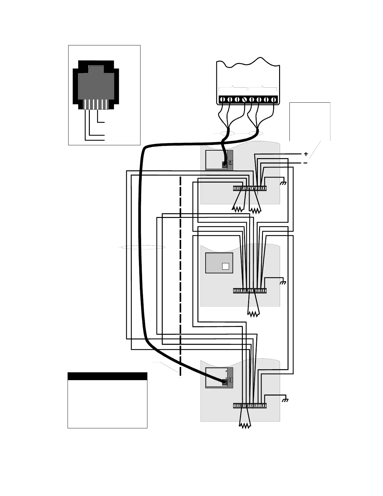
Wiring required for
Class A circuits only
RS-232 format communications
50ft (15.2M) max cable length.
Provide physical separation between
two wire bundles to ensure network
survivability
[XMDN-014.CDR]
CH A CH B
TTRT/R T/RRCC
FCOM-232
(INSTALLED IN DCPU)
RED
RED
YEL
YEL
WHT
WHT
1
NOTES
ALL WIRING SUPERVISED AND
POWER LIMITED.
2. ROUTE POWER LIMITED WIRING
SEPARATE AND AWAY FROM NON-
POWER LIMITED WIRING.
3. ALL WIRING 18 AWG, TWISTED.
4. UL LISTED 100 OHM EOL RESISTOR
(P/N 260071 or EOL-100) REQUIRED AT
PHYSICAL END OF RS-485 WIRING.
White (com)
Ye l low (R x)
Red (Tx)
NC
Top View, RJ11
on LSRA-232
NC
24 VDC FROM:
APS-4B(-220)
APS-8B
PS4B(-220)
PS8B
SIGA-APS
Figure Chapter 3-6: Class A FCC/DCPU Printer Port Wiring
LSRA Installation, Operation, Maintenance, and Configuration Manual 3.9