EasyManua.ls Logo

Et system LAB-HP/E Series - Ext. Control: AI Interface; Pin Assignment AI Interface

Et system LAB-HP/E Series
41 pages
Print Icon
To Next Page IconTo Next Page
To Previous Page IconTo Previous Page
Loading...
Ext. Control: AI Interface
ET System electronic GmbH 23
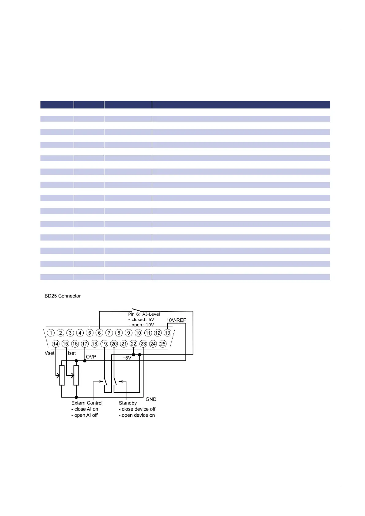
EXT. CONTROL: AI INTERFACE
The device can be controlled via control signals and by using the analog/digital In/Out.
PIN ASSIGNMENT AI INTERFACE
No (BD25)
Dir
Name
Function
1
analog out
U
mon
PRESET
Monitor set point U PRESET
2
analog out
I
mon
PRESET
Monitor set point I PRESET
3
-nc-
4
-nc-
5
-nc-
6
digital in
ATI level 5/10VDC
Set ATI level 5VDC or 10VDC
7
digital out
CV
Signals „Const. Voltage“ mode
8
analog out
U
istmon
Real value
Monitor output voltage Real on output
9
gnd
GND
-
10
digital out
Standby
Signals standby
11
gnd
GND
-
12
-nc-
13
REF 5/10
5-10 V-V
ref
Output 5/10 V reference voltage
14
analog in
U
set
Set point U
15
analog in
I
set
Set point I
16
-nc-
-
17
analog in
OVP
set
Set point OVP
18
-nc-
-
19
digital in
Ext. Control
Activates analog control
20
digital in
Standby
Activates standby
21
analog out
I
istmon
Real value
Monitor output current Real on output
22
pwr
+ 5 V
Output 5 V supply voltage
23
gnd
GND
-
24
digital out
Error
Signals shut down by OVP
25
gnd
GND
-
26
-nc-
-
-
All digital outputs are OC outputs with a pull-up resistance after + 5 V. All analog inputs and outputs can be operated
in 0-5 V or in 0-10 V mode.

Table of Contents