Sense Mode
ET System electronic GmbH 29
SENSE MODE
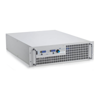
LOAD CONNECTION WITHOUT SENSOR CONDUCTOR
Almost all our power supplies are provided with sensor conductor connectors to compensate the voltage drop on the
load. In case, these connectors are not in use, they must be short-circuited with correct polarity to the load outputs
and directly to the output connectors. By no means, current may flow over the sense connectors. In case of multiple
loads, the user has to provide a central load distribution point. To reduce peak loads and for an HF impedance
terminator, a 1-10 µF capacitor should be connected to the output.
If thus you paid attention to the points stated above, oscillation occurs through load or power induction and complex
load situations, please contact our company ET System.
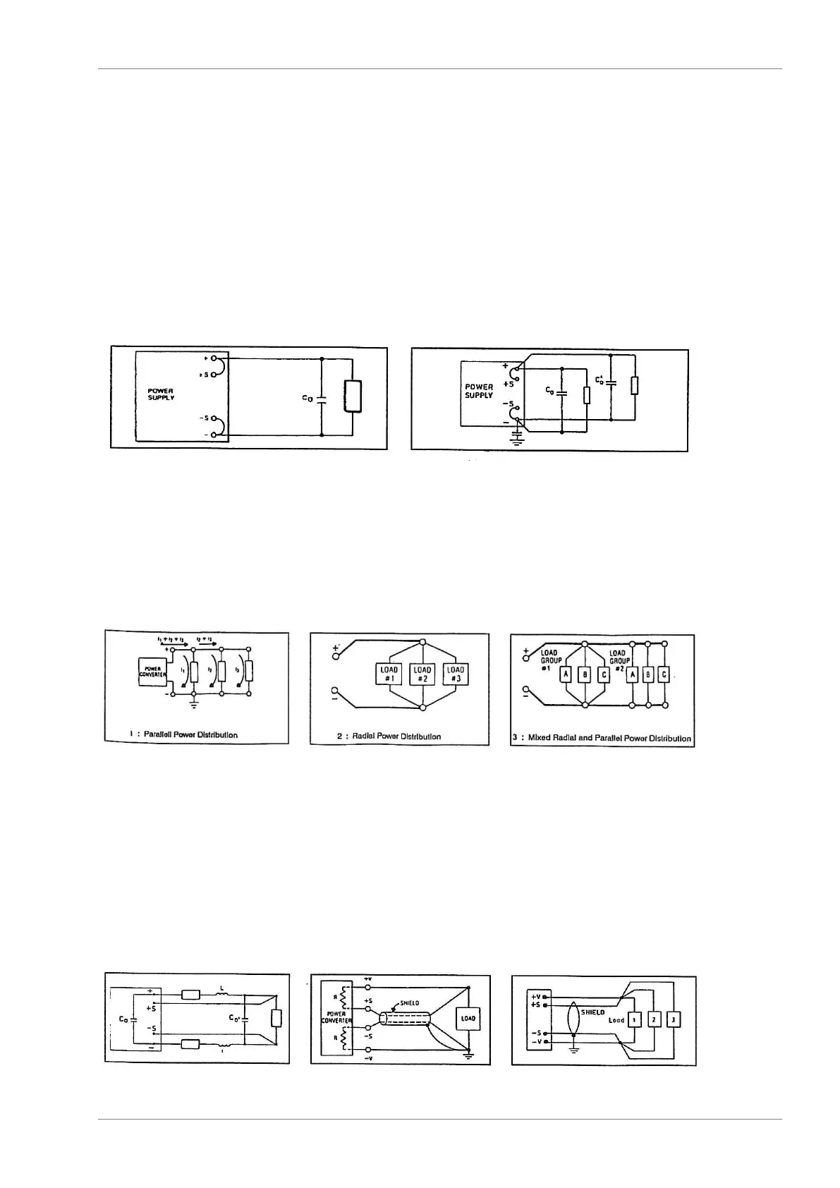
LOAD DISTRIBUTION WITHOUT SENSOR CONDUCTOR
To ensure a proper use, a central load distribution situation is essential. Illustration 2 shows a correct load
distribution. Illustration 1 shows an insufficient supply of load 2, load 3 etc. via parallel load conductors. In practice, it
may occur that an optimal distribution is not possible. Illustration 3 shows a mixed distribution, where at least the
largest consumers are supplied centrally.
LOAD CONNECTION WITH SENSOR CONDUCTOR
The following points must be considered, when existing sense cables are connected directly to the load or to the
central load distribution point:
remove existing sense cable bridges from the power supply
directly connect + sense and - sense with correct polarity to the load distribution point
connect + sense and - sense conductors to a 1-47 µF capacitor
protect sense cable or at least twist + sense and - sense
select load line cross section, so that voltage drop is < 0.4 V
avoid overload of power supplies (voltage drop per line x current)
If thus you paid attention to the points stated above, oscillation occurs through load or power induction and complex
load situations, please contact our company ET System.