Echoflex Installation Guide
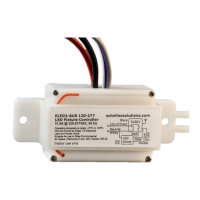
LED Fixture Controller (120-277 VAC)
6. Connect the gray and the violet wires to the driver or ballast’s
dimming interface (optional).
7. Restore power to the circuit.
Note:
The USB port is for factory use only. Do not attach cables
or accessories to this port.
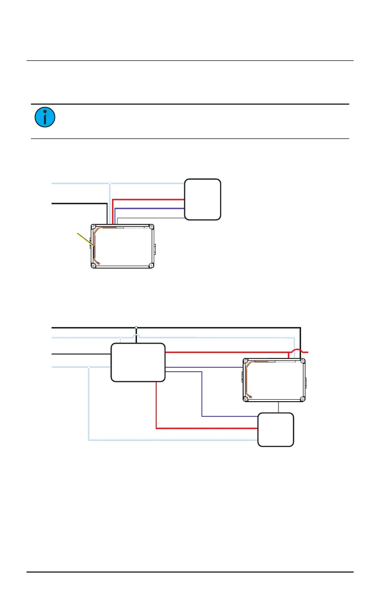
Wiring Diagram
Max. Switching Load:
11.5A @ 120-277 V, 50/60 Hz
Electronic Ballast or LED Driver
LED Driver
ELED1
Antenna (orange)
Do not cut
or cap
Load (red),
Switched Line (Hot)
Dimming 0-10 V (violet)
Dimming COM (gray)
Neutral (white)
Max. Dimming Load: 100 mA sinking
Max. Impulse Voltage: 4000 V
Internal Relay: Type 1.C
Dimming output is Class 1 circuit
Independently mounted control for
panel mount/surface mount
Line Hot (black),
120-277 V
Diagram for Emergency Fixtures 1 of 2
ELED1
LED Driver
LED Driver Neutral
Normal Control Sense
Dimming +
Dimming +
Normal
Emergency
Load
UL924 Emergency
Bypass Relay
(Echoflex EREB-AD)
Normal Neutral
Emergency Line (Hot)
Emergency Neutral
Normal Line (Hot)
Dimming -
Dimming -
LED Driver Hot
ELED1
Load Control
Normal
Luminaires
LED Fixture Controller (120-277 VAC) Page 4 of 12 Echoflex