Echoflex Installation Guide
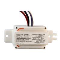
LED Fixture Controller (120-277 VAC)
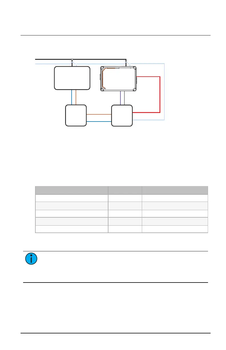
Diagram for Emergency Fixtures 2 of 2
Normal Line (Hot)
Normal Neutral
ELED1
Dimming + Dimming - LED +LED -
LED -
LED
Emitter
Board
LED
Driver
LED +
Battery
Backup
LED Driver HotLED Driver Hot
LED Driver NeutralLED Driver Neutral
ELED1 Load
Control
ELED1 Load
Control
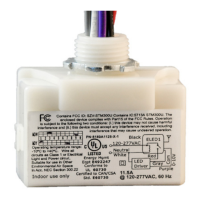
Electrical Terminations
Power to the controller is connected between the white (neutral) and the
black line power (120–277VAC). The Class 1 power limited dimming
lines (violet and gray wires) can be used to provide 0–10V intensity
control of a dimming ballast or LED driver. The orange wire is an antenna:
Do not cut, cap, or connect this wire. Use only UL-approved wire when
making connections to the controller.
Connection Color Specification
Load Red 14AWG, 600V
Neutral White 14AWG, 600V
Line (hot) Black 14AWG, 600V
Dimming 0–10V Violet 18AWG, 600V
Dimming COM Gray 18AWG, 600V
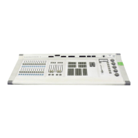
User Interface
Note:
Garibaldi Pro software is the ideal tool to set up your
project and configure settings, or even to make edits if your
project has been pre-commissioned. Garibaldi Pro is available for
download at echoflexsolutions.com.
Two buttons on the controller can be used to activate features and set
specific configurations directly on the device. Two LEDs beside the
buttons provide feedback about stored information and activities.
LED Fixture Controller (120-277 VAC) Page 5 of 12 Echoflex