25809-02A
16 - Assembly Procedures
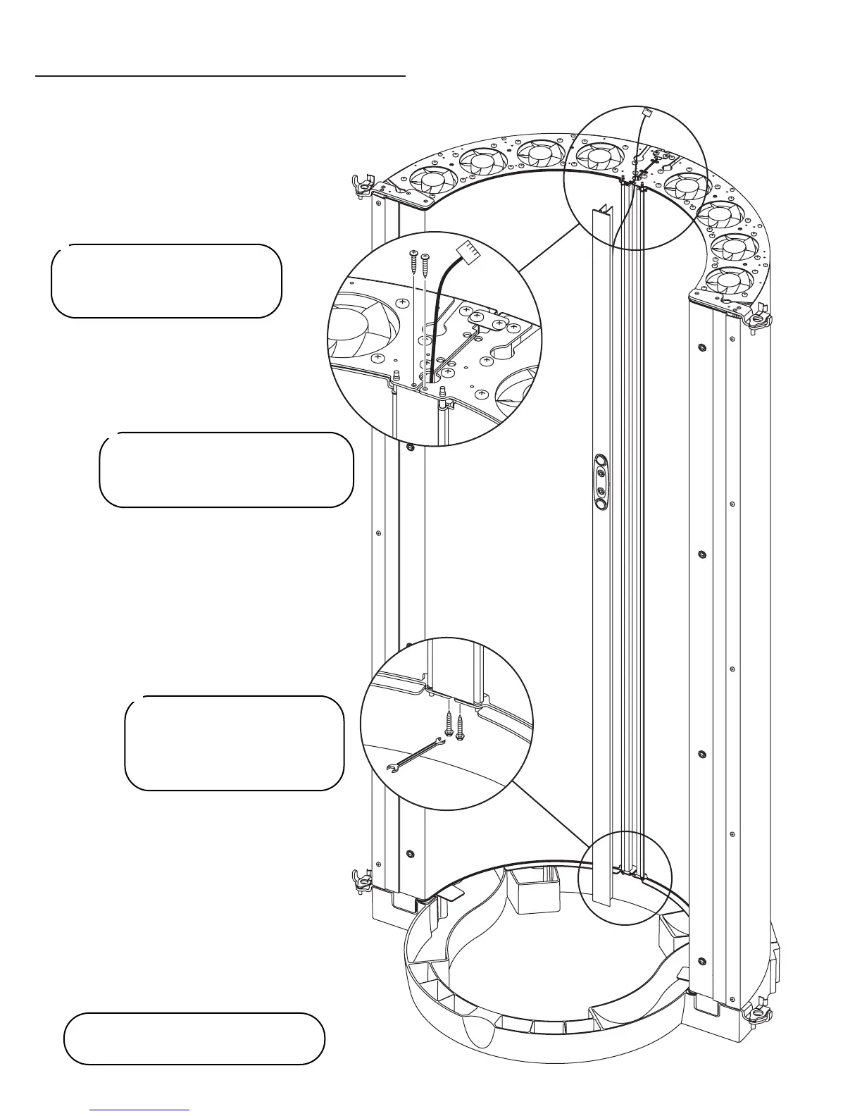
Parts needed:
Control Extrusion (box 1)
(2) #10 x 1” Phillips pan head screws
(2) #10 x 1” slotted hex washer head
screws
NOTE: Wiring and grills deleted
from illustration for clarity.
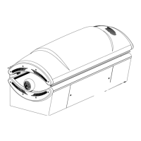
Feed the cable from the
Control Extrusion through the
hole between the modules).
1
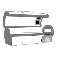
Press the Control Extrusion into
place and secure the top with the
pan head screws.
2
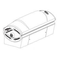
Secure the bottom of the
extrusion with the hex head
screws. Use a 5/16” wrench
or ratchet.
3