25809-02A
28 - Remote Connections
Setting the address manually
Before connecting your booth to the T-Max®
Manager or T-Max® 1A or 3A, the address of your
booth must first be set. Set the “id” manually as
described below.
Setting the Address
1. Make sure the booth display is showing
“0:00”.
2. Press the STOP button for three seconds. The
display should indicate an address number
from “1” to “255”.
3. If you are using a T-Max® 1A or 3A as a
“master” remote, the address of the booth
must be set to “1”. If you are using a T-Max®
Manager each sunbed must be assigned a
different address. To adjust the address, press
the START button to count up until the
desired number (from 1 to 128) is achieved.
Addresses 252 to 255 are not normally used.
4. Press the STOP button to return to the nor-
mal display mode.
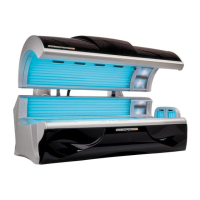
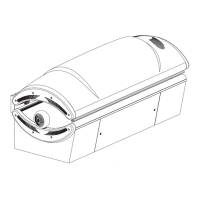
figure 3
Remote systems using a Control Relay
Most non-T-Max® remote systems control the unit
by the use of a relay. The relay operates the unit
by connecting and disconnecting a pair of wires
leading from the unit. Refer to the user’s manual
provided with your remote system to determine if
it operates in this way. To connect your booth to
this type of system a remote interface kit is
required. Contact your place of purchase to obtain
the kit. Figure 3 details a typical connection.
Follow the instructions provided with the kit and
from the remote’s manual to make the necessary
connections.
CAUTION
The remote connection is not designed to supply
or accept high voltage, nor can it provide power
to an external timer. The booth’s remote inter-
face circuitry operates on 5 volts, attempting to
connect it to any higher voltages will damage the
unit as well as void your warranty.
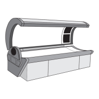
T-Max® 1A and 3A Remote Systems
In single sunbed installations, the T-Max® 1A and
3A can offer the same control as the T-Max®
Manager, eliminating the need for a Manager. If
you’re using a 1A in this manner, it must
have a
chip labelled “master” installed on its circuit
board. The remote control bypass plug must not
be used in this configuration. The 3A may be used
as a “master” with no modification.
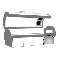
After you have set the T-Max® 1A’s, or 3A’s,
address to “0” (refer to your T-Max® user’s guide)
and the booth’s address to “1” (see below), simply
connect the RJ-22 modular cables, described in
the T-Max® user’s guide, directly into either port
located on the back of the unit and either port on
the back of the T-Max® 1A or 3A. See figure 2.
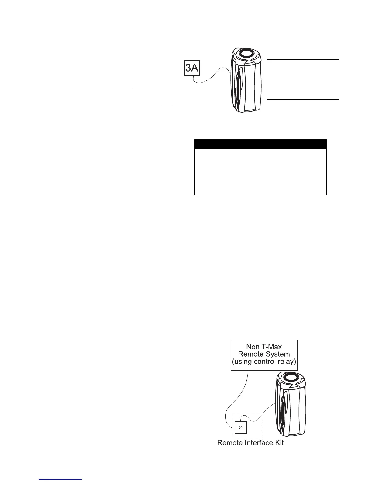
NOTE: A T-Max® 1A
with a “master” chip
can be substituted
for a 3A in figure 2.
figure 2