Operating Instructions
Non-Contact Safety Switch CES-I-BR-.-C07-…
8
(translation of the original operating instructions) 2510145-02-07/18
7. Installation
CAUTION
Safety switches must not be bypassed (bridging of contacts), turned away, removed or otherwise
rendered ineffective.
Ì Observe ENISO14119:2013, section 7, for information about reducing the possibilities for by-
passing an interlocking device.
NOTICE
Risk of damage to equipment and malfunctions as a result of incorrect installation.
Ì Safety switches and actuators must not be used as an end stop.
Ì Observe ENISO14119:2013, sections 5.2 and 5.3, for information about fastening the safety
switch and the actuator.
Ì From the assured switch-off distance S
ar
, the safety outputs are safely shut down.
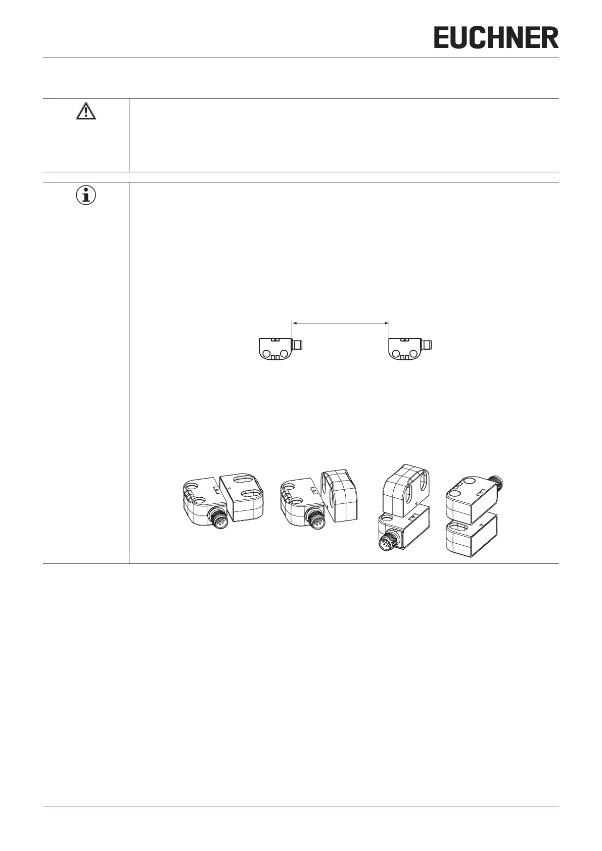
Ì When mounting several safety switches, observe the stipulated minimum distance to avoid mutual
interference.
.
min. 140 mm
Ì The operating distance changes during the mounting of the actuator as a function of the material
used for the guard.
Ì Observe direction of arrow on the device (see gure below).
Permissible approach directions
Note the following points:
Ì Actuator and safety switch must be easily accessible for inspection and replacement.
Ì Actuator and safety switch must be tted so that
- a minimum distance is maintained with a side approach direction to avoid entering the area of possible side lobes. See
chapter 11. Technical data, section Typical operating distance for the related actuator.
- when the guard is open up to the distance S
ar
(assured switch-off distance), a hazard is excluded.
- the actuator is positively mounted on the guard, e.g. by using the safety screws included.
- they cannot be removed or tampered with using simple means.
Ì Pay attention to the maximum tightening torque for the read head or safety switch and actuator mountings of 0.8Nm.
Ì Seal the mounting holes after mounting using the caps provided to prevent the accumulation of dirt.
Ì In order to avoid damage, the connection cable must be laid with protection in areas in which high-pressure cleaners are
used.

 Loading...


