37
2110788-13-03/20 (Translation of the original operating instructions)
Operating Instructions
Transponder-Coded Safety Switch CET.-AR-…
EN
11. Setup
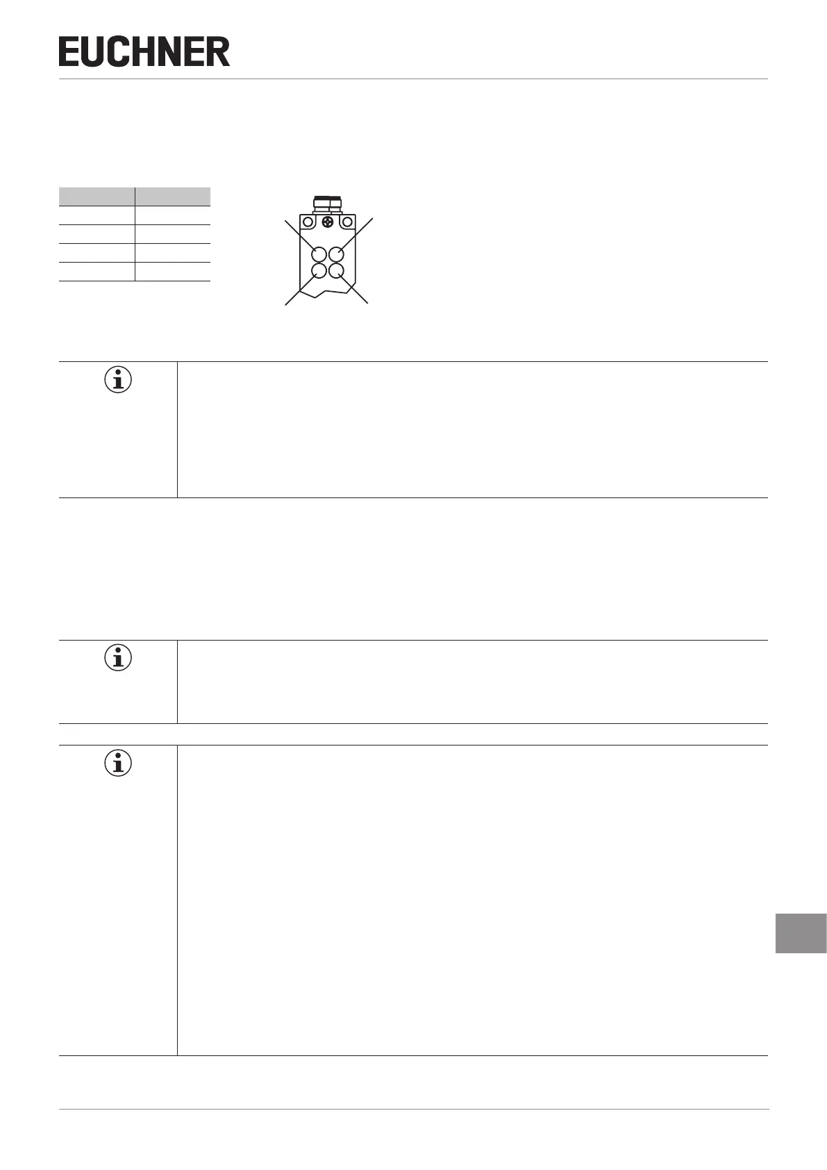
11.1. LED displays
You will nd a detailed description of the signal functions in chapter 12. System status table on page 41.
LED Color
STATE green
DIA red
LED 1 red
LED 2 green
NOTICE
Ì With hard-wired LEDs, the following applies:
- LED 1: red = Solenoid activated (voltage present at solenoid)
- LED 2: green = OUT D is switched on (door is closed)
Ì Depending on version, the function of LED1 and LED2 can differ. Detailed information is available
on the enclosed data sheet or at www.euchner.com. Simply enter the order number of your device
in the search box.
11.2. Teach-in function for actuator (only for unicode evaluation)
The actuator must be allocated to the safety switch using a teach-in function before the system forms a functional unit.
During a teach-in operation, the safety outputs and the monitoring output OUT are switched off, i.e. the system is in the
safe state.
Depending on the version, the teach-in operation is automatic or is performed with the aid of the teach-in input J.
Tip!
We recommend performing the teach-in operation prior to mounting. Mark switches and actuators that
belong together in order to avoid confusion. For devices to be connected in series, we recommend
performing the teach-in operation separately for each device prior to series connection.
Important!
Ì The teach-in operation may be performed only if the device functions awlessly. The red DIA LED
must not be illuminated.
Ì The safety switch disables the code of the preceding device if teach-in is carried out for a new
actuator. Teach-in is not possible again immediately for this device if a new teach-in operation is
carried out. The disabled code is released again in the safety switch only after a third code has
been taught-in.
Ì The safety switch can be operated only with the last actuator taught-in.
Ì Version without teach-in input: After starting, the device remains in teach-in standby state for
3min. If no new actuator is detected in this time, the device changes to normal operation. If the
switch detects the actuator that was most recently taught-in when in the teach-in standby state,
this state is ended immediately and the switch changes to normal operation.
Ì Version with teach-in input: Teach-in operation ends when the power supply to the teach-in input is
interrupted, but no later than after 3min. If no actuator is detected during this time, the device en-
ters the fault state. If the switch detects the actuator that was most recently taught-in when in the
teach-in standby state, this state is ended immediately and the switch changes to the fault state.
Ì The actuator to be taught-in is not activated if it is within the actuating range for less than 60s.
LED2 (gn)
STATE (gn) DIA (rd)
LED1 (rd)

 Loading...


