25
2110788-13-03/20 (Translation of the original operating instructions)
Operating Instructions
Transponder-Coded Safety Switch CET.-AR-…
EN
10.7.2. Version with door monitoring output (CET3/4)
Wiring diagram E
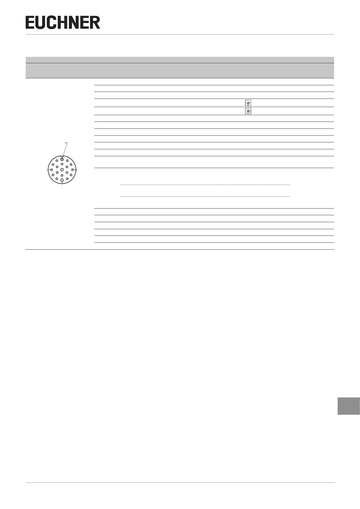
Plug connector
(view of connection side)
Pin Designation Function
Conductor coloring
of connecting
cable
1)
M23 (RC18)
With shield
spring
18
19
15
12
11
9
5
4
3
2
1
17
16 14
13
6
10
8
7
1 U
CM
Operating voltage of guard locking solenoid, 24VDC VT
2 IA Enable input for channel A RD
3 IB Enable input for channel B GY
4 OA
Safety output channel A
RD/BU
5 OB
Safety output channel B
GN
6 U
B
Operating voltage of AR electronics, 24VDC BU
7 RST Reset input GY/PK
8 OUTD Door monitoring output GN/WH
9 - n.c. YE/WH
10 OUT Monitoring output GY/WH
11 - n.c. BK
12
FE
Function earth:
This connection must be connected to 0V.
GN/YE
13
J
Version with teach-in input:
To teach-in a new actuator, connect to 24VDC; leave open in normal
operation.
2)
PK
Y
Version with feedback loop:
If the feedback loop is not used, connect to 24VDC.
-
Version without feedback loop and without teach-in input:
This connection must be connected to 0V.
14 - n.c. BN/GY
15 LED 1 LED 1 red, freely congurable, 24VDC BN/YE
16 LED 2 LED 2 green, freely congurable, 24VDC BN/GN
17 - n.c. WH
18 0V U
CM
Operating voltage of guard locking solenoid, 0V YE
19 0V U
B
Operating voltage of AR electronics, 0V BN
1) Only for standard EUCHNER connecting cable.
2) With dual-channel solenoid control, do not connect to 0VU
B

 Loading...


