Operating Instructions
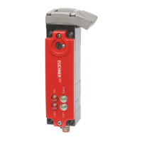
Transponder-Coded Safety Switch CTM-LBI-BR
16
(Translation of the original operating instructions) 2525462-01-01/20
9.6. Connector assignment, safety switch CTM-…-BR-…-SA-… with plug connector M12,
8-pin
Wiring diagram C
Plug connector
(view of connection side)
Pin Designation Function
Conductor coloring
of connecting ca-
ble
1)
1 x M12
8
5
6
7
2
4
3
1
1 FI1B Enable input, channel 2 WH
2 UB Operating voltage, 24VDC BN
3 FO1A
Safety output, channel 1
GN
4 FO1B
Safety output, channel 2
YE
5 OD/C Door monitoring output/communication GY
6 FI1A Enable input, channel 1 PK
7 0V Operating voltage, 0 V BU
8 IMP Control input of guard locking solenoid RD
1) Only for standard EUCHNER connecting cable.

 Loading...