System Manual Safety System MGB-AR in Combination with a Locking Module
18
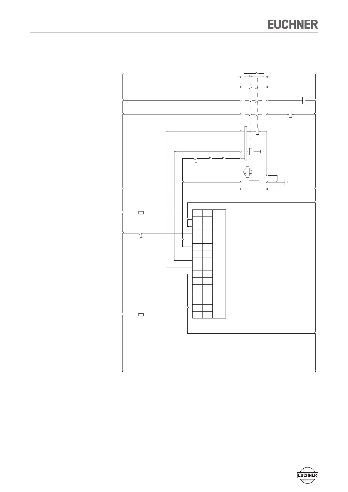
Operation as separate device
Figure 17: Connection example for separate operation
The switches can be reset via the RST input. To do this, a voltage of 24 V is ap
-
plied to the RST input for at least 3 seconds. The supply voltage to the switches
is interrupted during this time. The RST input must be connected to 0 V if it is not
used.
24V
GND
-F1
X5.6UB
X5.50V
X5.4OUT4
X5.3OUT3
X5.2OUT2
X5.1OUT1
X4.6RST
MGBL
X4.5OB
X4.4OA
X4.3---
X4.2IB
X4.1IA
Entriegeln/
Unlock
X3.7UCM
X3.60VM
X3.50VM
-F2
X3.4UA
A1
24V DC
A1
A2
S11
S10
ESM-BA3xx
S13
EUCHNER
Start
KA
KB
S21 S12
K1
+
S14
K2
+
13
14
KA
A1
A2
23
24
KB
A1
A2
33
34
41
42
 Loading...