System Manual Safety System MGB-AR in Combination with a Locking Module
20
Information on operation in a CES-AR switch chain
System times
The locking module has longer response times than a CES-AR switch (see Technical
data and diagram of Typical system times, Figure 20 and 21).
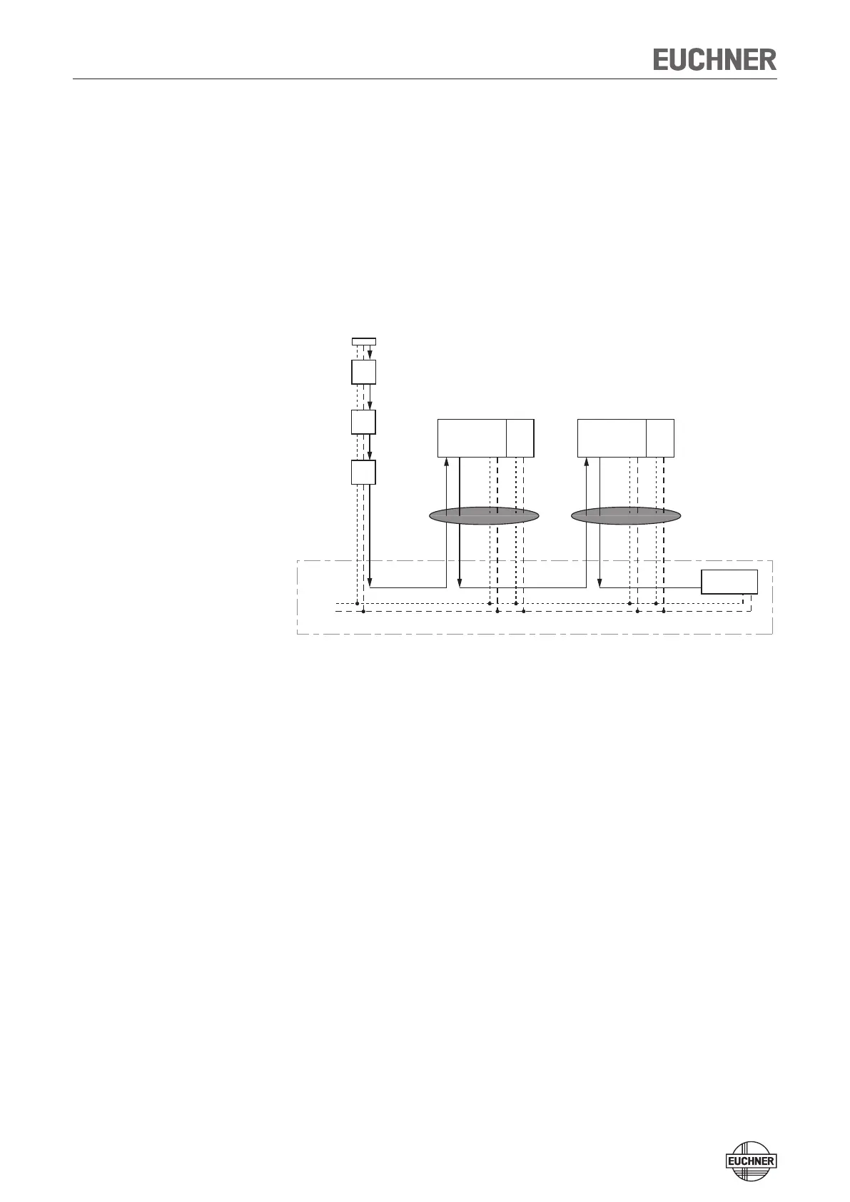
Position in a CES-AR switch chain
The locking module must be the last device in the CES-AR switch chain (see Figure
19).
Important: lay cables in a common harness
Figure 19: Position in a CES-AR switch chain
Output current
The safety outputs on the guard locking module have a lower maximum output
current than a CES-AR switch (see Technical data).
Number of devices in the switch chains
In a pure MGB switch chain a maximum of ten devices can be connected in series.
In mixed switch chains (e. g. together with CES-AR) the maximum number of devices
is also reduced to ten.
CES-AR
terminating plug
CES-AR
CES-AR
PLC
MGB-L.-AR...
+ 24 V DC
cabinet
0 V
I
A
/I
B
I
A
/I
B
O
A
/O
B
O
A
/O
B
I
A
/I
B
I
A
/I
B
O
A
/O
B
U
B
0V
U
A
0V
O
A
/O
B
#1
#2
#3
#4
MGB-L.-AR...
I
A
/I
B
O
A
/O
B
U
B
0V
U
A
0V
#5
 Loading...