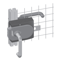
System Manual Safety System MGB-AR in Combination with a Locking Module
24
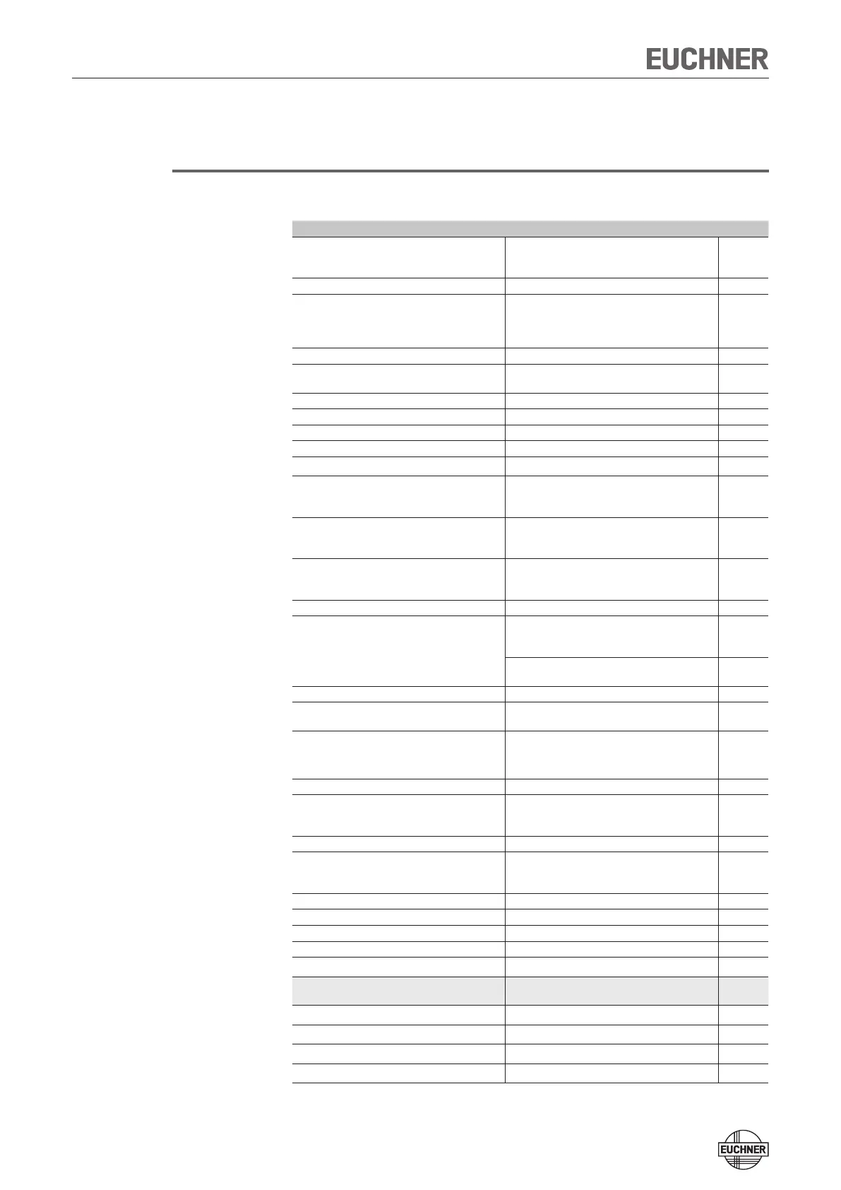
Technical Data
Note!
If a product data sheet is included with the product, the information on the data
sheet applies in case of discrepancies with the operating instructions.
Parameter Value Unit
Housing material Glass fiber reinforced plastic
die-cast zinc, nickel-plated
Stainless steel
Dimensions See dimension drawing
Weight
Locking module
Handle module
Escape release
0,75
1,00
0,50
kg
Ambient temperature at U
B
= DC 24 V -20 .... +55 °C
Degree of protection
- on usage of key-operated switches
IP 54
IP 42
Safety class III
Degree of contamination 3
Installation position Any
Locking force F
zh
according to GS-ET-19 2000 N
Connection type
4 cable entries M20x1.5 or plug connector RC18
Conductor cross-section (rigid/flexible)
- with ferrule according to DIN 46228/1
- with ferrule with collar according to DIN 46228/1
0.13 ... 1.5 (AWG 24 ... AWG 16)
0.25 ... 1.5
0.25 ... 0.75
mm²
Operating voltage U
B
(reverse polarity protected, regulated, residual
ripple < 5 %)
24 +10% / -15% (PELV)
V DC
Auxiliary voltage U
A
(reverse polarity protected, regulated, residual
ripple < 5 %)
24 +10% / -15% (PELV)
V DC
Current consumption I
UB
(no load on any outputs) 80 mA
Current draw with interlocking solenoid I
UA
(with
energized interlocking solenoid and unloaded
outputs O1 ... O4)
350
mA
- Additional current consumption for version with
controls and indicators in the cover
Max. 20
mA
External fuse See page 16 "Fuse protection for power supply"
Safety outputs OA/OB Semiconductor outputs, p-switching, short
circuit-proof
Output voltage U
OA
/U
OB
1)
HIGH U
OA
/ U
OB
U
B
-2V ... U
B
LOW U
OA
/ U
OB
0 ... 1 V DC
Switching current per safety output 1 ... 200 mA
Utilization category according to EN IEC 60947-
5-2
DC-13 24 V 200 mA
Caution: outputs must be protected with a free-
wheeling diode in case of inductive loads.
Classification acc. to EN IEC 60947-5-3
PDF-M
Monitoring outputs
- Output voltage
1)
- Max. load
p-switching, short circuit-proof
U
A
- 2V ... U
A
Max. 200 mA
Rated insulation voltage U
i
30 V
Rated impulse withstand voltage U
imp
1,5 kV
Resilience to vibration As per EN IEC 60947-5-3
Switching frequency 1 Hz
EMC protection requirements
As per EN IEC 60947-5-3
Reliability figures according to EN ISO
13849-1
Category
4
Performance Level
PL e
PFH
d
2.4 x 10
-9
/ h
2)
Mission time
20
years
1) Values at a switching current of 50 mA without taking into account the cable lengths.
2) Applying the limit value from EN ISO 13849-1:2008, section 4.5.2 (MTTF
d
= max. 100 years), BG certifies a PFH
d
of max.
2.47 x 10
-8
.
 Loading...