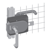
System Manual Safety System MGB-AR in Combination with a Locking Module
19
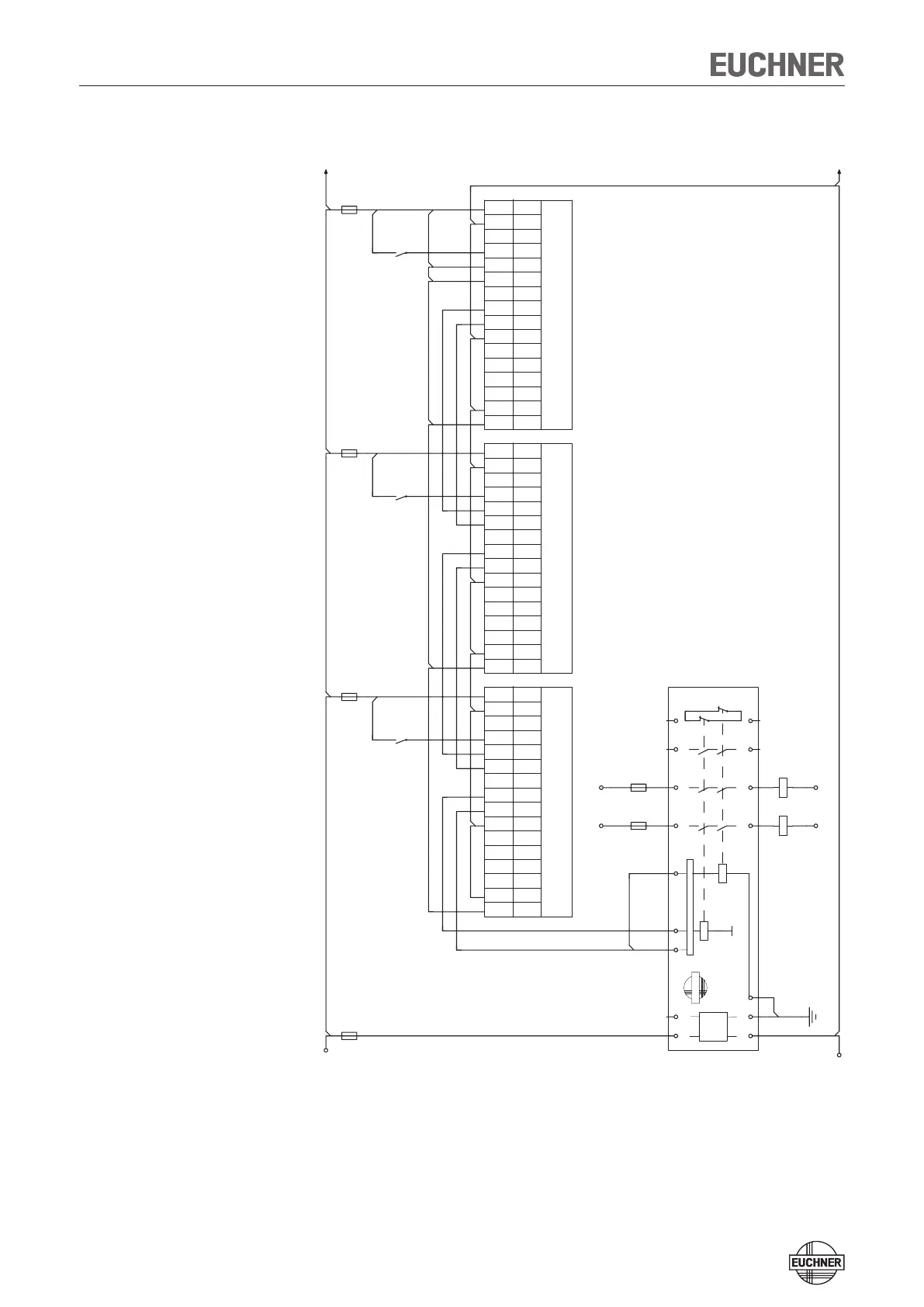
Operation in a CES-AR switch chain
Figure 18: Connection examples for operation in a CES-AR switch chain
For detailed information on operation in a CES-AR switch chain, see the related
CES-AR system manual. The locking module MGB-L1-AR-.../MGB-L2-AR-... behaves
in the switch chain in practice like a safety switch CES-AR. The differences to the
CES-AR are described in the following.
GND
DC 24 V
A1
24VDC
F1
A1
A2
S11
S10
ESM-BA3xx
S13
EUCHNER
S21 S12
K1
+
UBX5.6
0VX5.5
O4X5.4
S14
K2
+
O3X5.3
O2X5.2
O1X5.1
F5
13
14
K5
RSTX4.6
OBX4.5
MGB-L1-AR... #3
OAX4.4
F6
23
24
K6
NCX4.3
IBX4.2
IAX4.1
33
34
UCMX3.7
NCX3.6
41
42
0VMX3.5
F2
UAX3.4
UBX5.6
0VX5.5
O4X5.4
O3X5.3
O2X5.2
O1X5.1
RSTX4.6
OBX4.5
MGB-L1-AR... #2
OAX4.4
NCX4.3
IBX4.2
IAX4.1
UCMX3.7
NCX3.6
0VMX3.5
-F3
ACHTUNG: Rückführkreis muss entsprechend Risikobeurteilung eingebunden werden.
UAX3.4
UBX5.6
0VX5.5
O4X5.4
O3X5.3
O2X5.2
O1X5.1
RSTX4.6
OBX4.5
MGB-L1-AR... #1
OAX4.4
NCX4.3
IBX4.2
IAX4.1
UCMX3.7
NCX3.6
0VMX3.5
F4
UAX3.4
ATTENTION: Feedback loop must be integrated according to risk assessment.
 Loading...