6
Operating Instructions
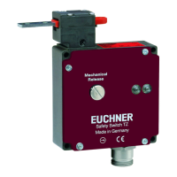
Safety Switch TZ…
Scope
These operating instructions are valid for all safety
switches TZ…. These operating instructions, the
document Safety information and maintenance and
any enclosed data sheet form the complete user
information for your device.
Supplementary documents
The overall documentation for this device consists
of the following documents:
Document title
(document number)
Contents
Safety information
(2525460)
Basic safety information
Operating instructions
(2088062)
(this document)
www
Declaration of con-
formity
Declaration of conformity
www
Any additions to the
operating instructions
Take any associated additions to
the operating instructions or data
sheets into account.
www
Important!
Always read all documents to gain a complete
overview of safe installation, setup and use of
the device. The documents can be downloaded
from www.euchner.com. For this purpose, enter
the doc. no. or the order number for the device
in the search box.
Correct use
Safety switches series TZ are interlocking devices
with guard locking solenoid (type2). The actuator
has a low coding level. In combination with a movable
guard and the machine control, this safety compo-
nent prevents the guard from being opened while
a dangerous machine function is being performed.
This means:
f Starting commands that cause a dangerous ma-
chine function must become active only when the
guard is closed and locked.
f The guard locking must not be released until the
dangerous machine function has ended.
f In applications for the protection of persons, the
position of the guard locking must be monitored by
evaluating the contact for the solenoid monitoring
(ÜK) in the safety circuit.
f Closing and locking a guard must not cause auto-
matic starting of a dangerous machine function.
A separate start command must be issued. For
exceptions, refer to ENISO 12100 or relevant
C-standards.
Devices from this series are also suitable for process
protection.
Before the device is used, a risk assessment must
be performed on the machine, e.g. in accordance
with the following standards:
f ENISO13849-1
f ENISO12100
f IEC62061
Correct use includes observing the relevant require-
ments for installation and operation, particularly
based on the following standards:
f ENISO13849-1
f ENISO14119
f EN60204-1
Important!
f The user is responsible for the proper integration
of the device into a safe overall system. For this
purpose, the overall system must be validated,
e.g. in accordance with ENISO13849-2.
f If the simplified method according to section 6.3
of ENISO13849-1:2015 is used for determining
the Performance Level (PL), the PL might be re-
duced if several devices are connected in series.
f Logical series connection of safe contacts is
possible up to PLd in certain circumstances.
More information about this is available in
ISOTR24119.
f If a data sheet is included with the product, the
information on the data sheet applies in case of
discrepancies with the operating instructions.
Safety precautions
WARNING
Danger to life due to improper installation or due
to bypassing (tampering). Safety components
perform a personnel protection function.
f Safety components must not be bypassed,
turned away, removed or otherwise rendered
ineffective. On this topic pay attention in partic-
ular to the measures for reducing the possibility
of bypassing according to ENISO14119:2013,
section 7.
f The switching operation must be triggered only
by actuators designated for this purpose.
f Prevent bypassing by means of replacement
actuators. For this purpose, restrict access to
actuators and to keys for releases, for example.
f Mounting, electrical connection and setup only
by authorized personnel possessing special
knowledge about handling safety components.
CAUTION
Danger due to high housing temperature.
f Protect switch against touching by personnel or
contact with flammable material.
Function
The safety switch permits the locking of movable
guards.
The switch contains a rotating switching disk and a
locking arm that block/release the guard locking pin.
The guard locking pin is moved on the insertion/
removal of the actuator and on the activation/
release of the guard locking. During this process
the switching contacts are actuated.
If the guard locking pin is blocked (guard locking
active), the actuator cannot be pulled out of the
switch head. For design reasons, guard locking
can be activated only when the guard is closed
(prevention of inadvertent locking position (faulty
closure protection)).
Position monitoring of the guard and monitoring
of interlocking are performed via two separate
switching elements.
SK ÜK
123456
GN RD
Fig. 1: Function of safety switch TZ
The safety switch is designed so that fault ex-
clusions for internal faults in accordance with
ENISO13849-2:2012, TableA4, can be assumed.
Guard lock monitoring
All versions feature at least one safe contact for
monitoring guard locking. The contacts are
opened when guard locking is released.
Door monitoring contact
All versions additionally feature at least one door
monitoring contact. Depending on the switching
element, the door monitoring contacts can be
either positively driven (contacts ) or not posi-
tively driven.
The door monitoring contacts are actuated when
the guard is opened.
Version TZ1
(guard locking actuated by spring force and released
by power-ON)
f Activating guard locking: close guard; no voltage
at the solenoid
f Releasing guard locking: apply voltage to the
solenoid
The spring-operated guard locking functions in ac-
cordance with the closed-circuit current principle. If
the voltage is interrupted at the solenoid, the guard
locking remains active and the guard cannot be
opened directly.
If the guard is open when the power supply is
interrupted and is then closed, guard locking is
activated. This can lead to persons being locked
in unintentionally.
Version TZ2
(guard locking actuated by power-ON and released
by spring force)
Important!
f Guard locking devices according to the open-cir-
cuit current principle are not intended for pro-
tecting personnel.
f Use as guard locking for personnel protec-
tion is possible only in special cases, after
strict assessment of the accident risk (see
ENISO14119:2013, section 5.7.1)!
f Activating guard locking: apply voltage to the
solenoid
f Releasing guard locking: disconnect voltage from
the solenoid
The magnetically actuated guard locking operates in
accordance with the open-circuit current principle. If
the voltage at the solenoid is interrupted, the guard
locking is released and the guard can be opened
directly!
Switching states
The detailed switching states for your switch can
be found in Fig. 5. All available switching elements
are described there.
Guard open
The safety contacts and are open.
Guard closed and not locked
The safety contacts are closed. The safety
contacts are open.
Guard closed and locked
The safety contacts and are closed
.
Selection of the actuator
NOTICE
Damage to the device due to unsuitable actuator.
Make sure to select the correct actuator.
Additionally pay attention to the door radius and the
mounting options (see Fig. 6).
 Loading...