9
Operating Instructions
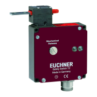
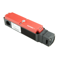
Safety Switch TZ…
Fig. 4: Dimension drawing TZ…
With escape release
Key to symbols
/
Guard locking ready for operation
/
Guard locking released
a
RDGN
0,3
0,3
M20x1,5
41
31
Ø 5,5
31
52
0
36
23
36 25
20
46
37
15
M8
100
110
100
110
35
20
40
41,5
22
12,5
M=1,2Nm (4x)
M=1,2Nm (4x)
18
Illustration:
TZ.R.. Actuating head on the right
(actuating head on the left is a mirror image)
a Travel without operation:
Actuator is in the guide slot, but a
function is not triggered.
b Switching operation com-
pleted:
Actuator must be inserted to this
point to ensure safe switching. The
actuator must be withdrawn at least
to point a for switching off.
Auxiliary release
Auxiliary release with triangular wedge
(2 triangular keys included)
Auxiliary release with pushbutton
42
35
48
61
5
15
10
16,5
40
L1
~ L2
Actuated
Length of escape release
Type L1 L2
TZ…C2381 75
69
TZ…C2372 106
100
 Loading...