7700 MultiFrame Manual
7700FC VistaLINK® Frame Controller
7700FC-2 Revision 1.4.7
2. INSTALLATION
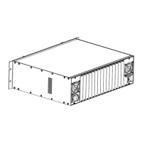
The 7700FC Frame Controller module can only be installed into 7700FR-C frames that have been fitted
with the proper module interconnect circuit board. These frames have an ‘L’ shaped cover plate installed,
adjacent to the IEC power inlet connector as shown in Figure 2. If your frame does not have this L shaped
cover plate then the 7700FC Frame controller card can not be installed in this frame.
Figure 2: 7700FR-C Rear Panel with Cover Plate Installed
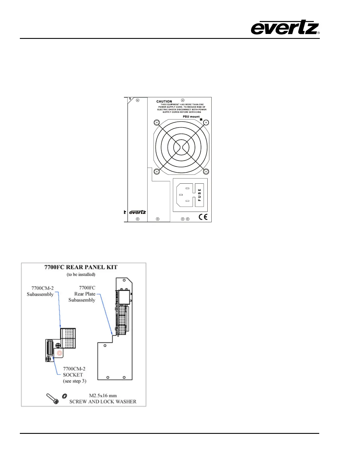
2.1. INSTALLING THE MODULE REAR PLATE
The 7700FC rear panel kit consists of a screw and lock
washer, and two subassemblies, the 7700CM-2
connector module and the 7700FC rear panel plate
which houses the appropriate connectors for the module.
To install the 7700FC rear panel kit, locate the slot 1 at
the right side of the frame rear panel. Remove the filler
plates from the slot as shown in step 1 of Figure 3.
Install the 7700CM-2 subassembly first. Remove the
screw PART 1 as shown in Step 2. Carefully align the
7700CM-2 socket with the frame header and press firmly
into place as shown in step 3. Secure the 7700CM-2
subassembly with the M2.5x16 mm screw and M2.5 lock
washer as shown in Step 4.
Orient the 7700FC plate so that the labeling is visible
when the plate is installed (see Step 5). Loosely fasten
the plate to the extrusions using the mounting screws
you removed in Step 1. You will tighten the screws after
the main module is installed.