7700 MultiFrame Manual
7700FC VistaLINK® Frame Controller
7700FC-4 Revision 1.4.7
2.2. INSTALLING AND REMOVING THE MODULE
In order to insert or remove modules you will have to open the front panel. Turn the two captive screws
located on the front panel counter clockwise several turns until they release completely from the front
extrusions. Carefully lower the front panel door so that the front edge of the door is lower than the rear of
the door.
To install the frame controller module, orient the module vertically such that the white card ejector is on the
bottom. Align the card with the card guide corresponding to the slot number where you installed the rear
panel plate. Carefully slide the module into the frame and press it completely into the rear panel
connectors. Make sure that the connectors are fully seated in the rear panel. When this is done, close the
front panel and then tighten the screws that hold the rear panel in place.
To remove the frame controller module, press the card ejector down to release the module from the back
panel connectors. Grasp the card using the card ejector and pull the module out from the frame. As the
card ejector goes past the front extrusion, you will have to pull it with slightly more force. Carefully place
the module in a safe place, free from static discharge.
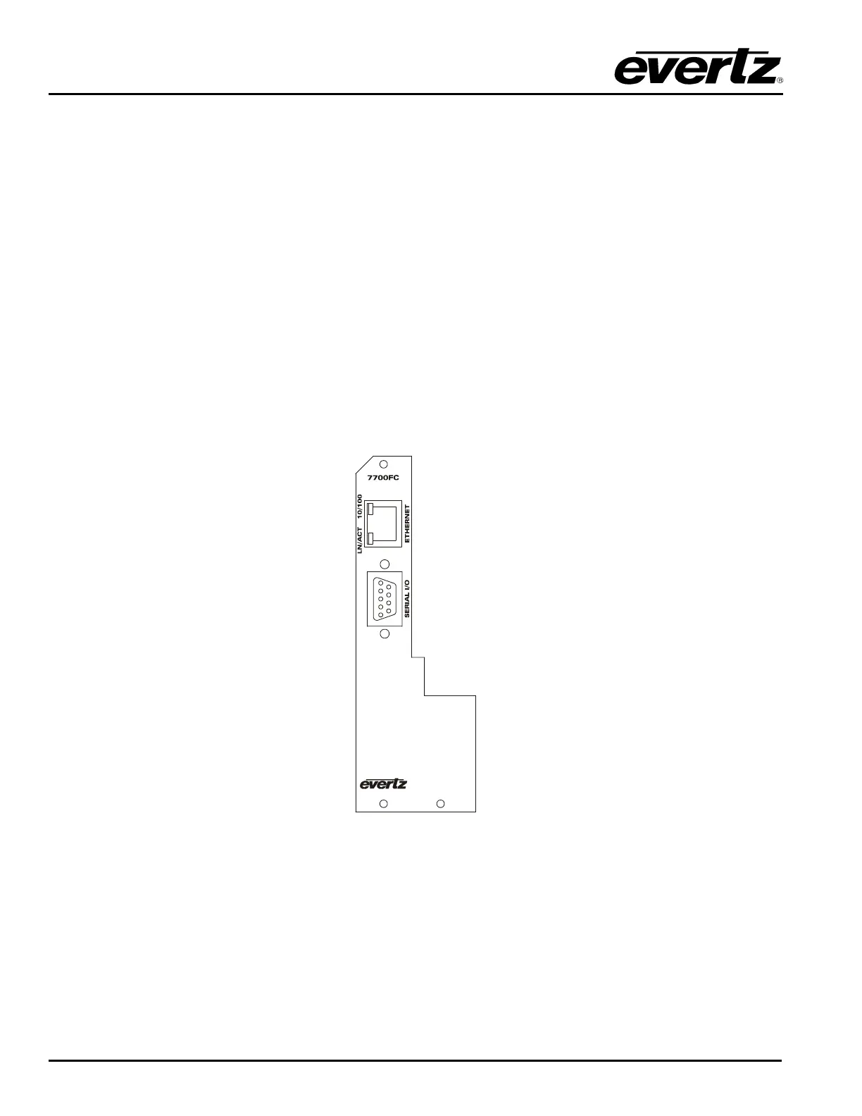
2.3. REAR PANEL CONNECTIONS
Figure 4: 7700FC Rear Panel
2.3.1. Ethernet Connection
The 7700FC is designed to be used with either 10Base-T (10 Mbps) or 100Base-TX (100 Mbps) also
known as Fast Ethernet, twisted pair Ethernet cabling systems. When connecting for 10Base-T systems,
category 3, 4, or 5 UTP cable as well as EIA/TIA – 568 100Ω STP cable may be used. When connecting
for 100Base-TX systems, category 5 UTP cable is required. The cable must be “straight-through” with a
RJ-45 connector at each end (See Table 1). Make the network connection by plugging one end of the