280
MIDSECTION
EXHAUST HOUSING
V4 MODELS
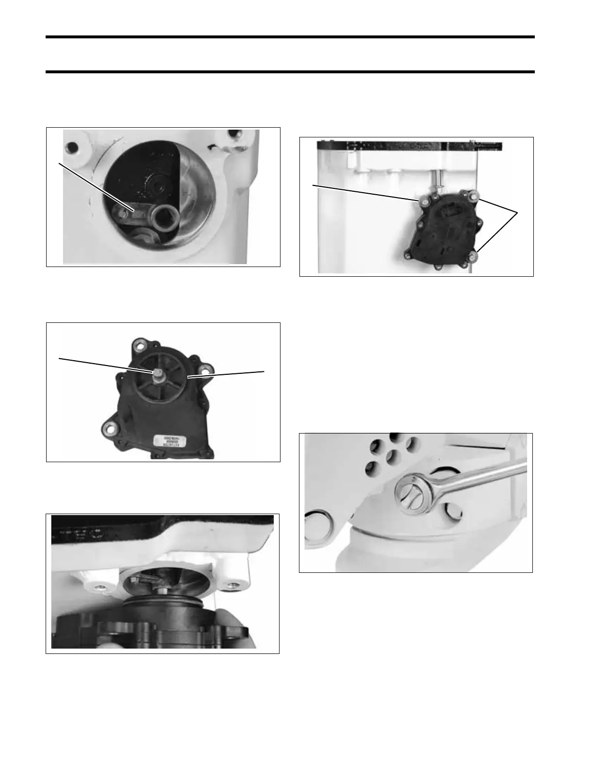
Check that exhaust valve linkage is oriented as
shown. “OUT” marking on lever must be visible.
Apply a small amount of Triple-Guard grease to
the actuator shaft and o-ring.
Carefully engage actuator shaft in linkage lever.
Rotate and push actuator into position. Apply Tri-
ple-Guard grease to screw threads and install
screws and washers. Tighten screws to 60 to 84
in. lbs. (7 to 9.5 N·m).
IMPORTANT: Fill actuator electrical connec-
tors with Electrical Grease before installation.
Exhaust Housing Installation
Bring the exhaust housing into position with the
stern bracket.
Install four new lower mount screws with lock-
patch. Tighten screws to a torque of 38 to 45 ft.
lbs. (51 to 61 N·m).
Install powerhead. Refer to POWERHEAD
INSTALLATION on p. 251.
Install gearcase. Refer to Gearcase GEARCASE
REMOVAL AND INSTALLATION on p. 301.
1. “OUT” mark 005208
1. Shaft
2. O-ring
005209
005219
1
2
1
1. Actuator screws 005206
23036
1
1