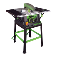
Forwards and backwards adjustment of the rip fence is possible.
Loosen the two finger nuts and slide the aluminium extrusion
to the desired position. Tighten the finger nuts securely.
Note: We recommend that normally the rip fence be adjusted
so that the rear of the guide is level with the rear of the blade
where it emerges from the table. See Fig 21.
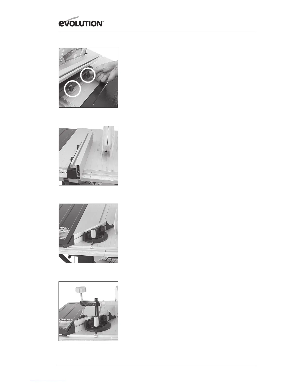
Note: If the rip fence is used on the LH side of the blade
the aluminium extrusion will have to be repositioned to
the RH side of the steel box-section carrier.
Undo the two wing nuts and remove the aluminium extrusion
with its bolts in place. Reposition the extrusion on the RH side
of the steel carrier and re-attach the wing nuts. See Fig 22.
Adjust as above.
Remember to return to the original configuration when the rip
fence is in the normal (RH) operating position.
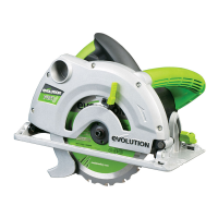
5. Mitre Gauge
The mitre gauge can be used on either side of the table and
runs in two inverted T slots in the table top.
Turn the vertical handle counter-clockwise to unlock
the mitre gauge, and adjust to the required angle.
Turn the handle clockwise to lock the mitre gauge
at the chosen angle. See Fig 23.
Note: The extruded aluminium face plate of the mitre
gauge should be adjusted so that it is close to, but does not
foul the blade guard. Adjust by loosening the two wing nuts
and sliding the faceplate to the required position. Securely
tighten the wing nuts.
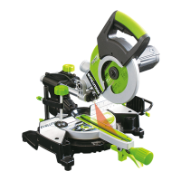
6. ANTIBOUNCE DEVICE
If required, when cutting thin sheet or thin walled box-section
material (maximum 3mm thickness applies when Steel cutting),
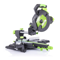
the anti-bounce device can be employed. See Fig 24. Adjust
using the adjustable handle and knob for best position.
Note: Adjust the anti-bounce device so that the head does
not quite touch the material to be cut. You can achieve this by
gently clamping the material to be cut with the anti-bounce
device, and then backing off the head by 1/4 to1/2 a turn.
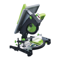
Fig 21
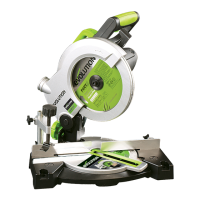
Fig 22
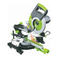
Fig 23
Fig 24