1. ASSEMBLY OF THE TABLE STAND
Note: This process can be considerably aided by studying the
images of an assembled machine as found on the original box
packaging.
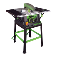
Eight cross-pieces are supplied (See Fig 1). The black cross-
pieces are for the top of the stand, the green ones are for mid
way fixing. The cross-pieces are paired, with two long and two
short of each colour.
Identify all parts before proceeding with assembly.
1. Fit the flexible rubber feet to the four legs. The two
turned over metal tabs should be guided into the two
25mm slots in the base of the rubber foot which can
then be moulded around the base of the leg.
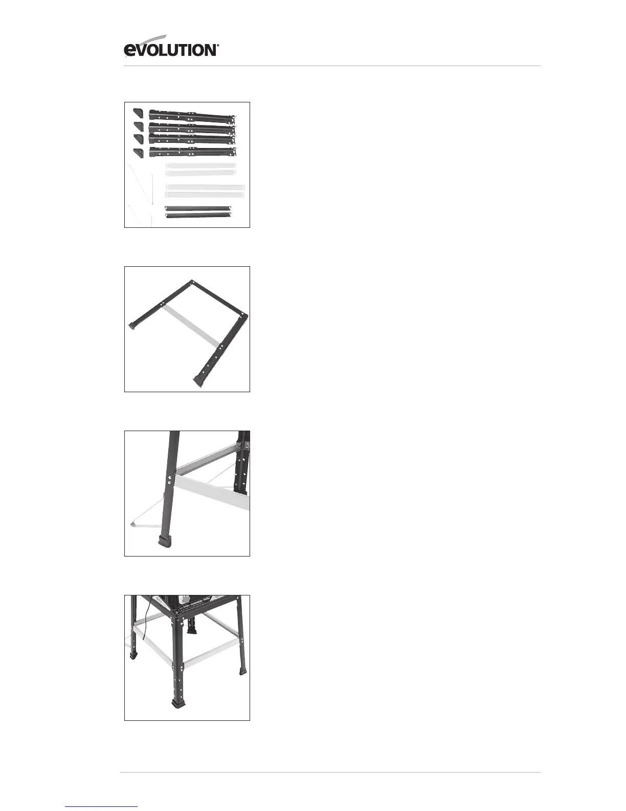
2. Select two legs, a long top cross-piece and a long green
cross-piece. Fit the top cross-piece to each leg using one
6mm hex bolt, ensuring that the locating lug on the cross-piece
engages into the rectangular slot in the top of the leg. Fit the
green cross-piece using four 6mm hex bolts. This cross-piece
has sloped ends to accommodate the splay of the legs. Ensure
it is fitted correctly with slope facing upwards. Do not fully
tighten any of the bolts at this stage. This assemblage will
become a side of the stand and should resemble a flat
topped letter ‘A’. See Fig 2.
3. Repeat the above to produce a second side.
4. Using the remaining two top cross-pieces and two green
cross-pieces, join the sides together to form the rectangular
base of the table stand.
Ensure that the mounting holes formed by the top cross-pieces
at each corner of the stand are in alignment. The machine
mounting bolts can be loosely fitted in place as an aid to
alignment. (Front ø6mm x 30mm, rear ø6mm x 55mm)
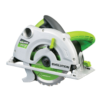
5. Fit the two cantilever braces to a narrow side. This will
become the rear of the stand. These will provide extra
stability and safety when the saw is in use See Fig 3.
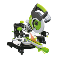
When finally satisfied with the construction, tighten all nuts
and bolts securely, and remove the mounting bolts from the
corner holes. See Fig 4.
Fig 1
Fig 2
Fig 3
Fig 4