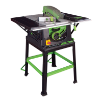
2. ATTACHING THE MAIN BODY TO THE STAND
WARNING: This machine is heavy, enlist competent
help when fastening this machine to its base.
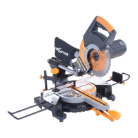
The main body of the saw can now be attached to the stand
using the four bolts, washers and nuts provided. Ensure that the
saw is attached to the stand the correct way round. The bolts
fasten through the machines four corner mounting holes, and
through the four corner holes in the stand. See Fig 5.
3. TABLE EXTENSIONS
Note: The pressed steel table extensions are not handed
and can fit on either side of the machine. However the
single hole in the end of the extensions should be to
the front of the saw table.
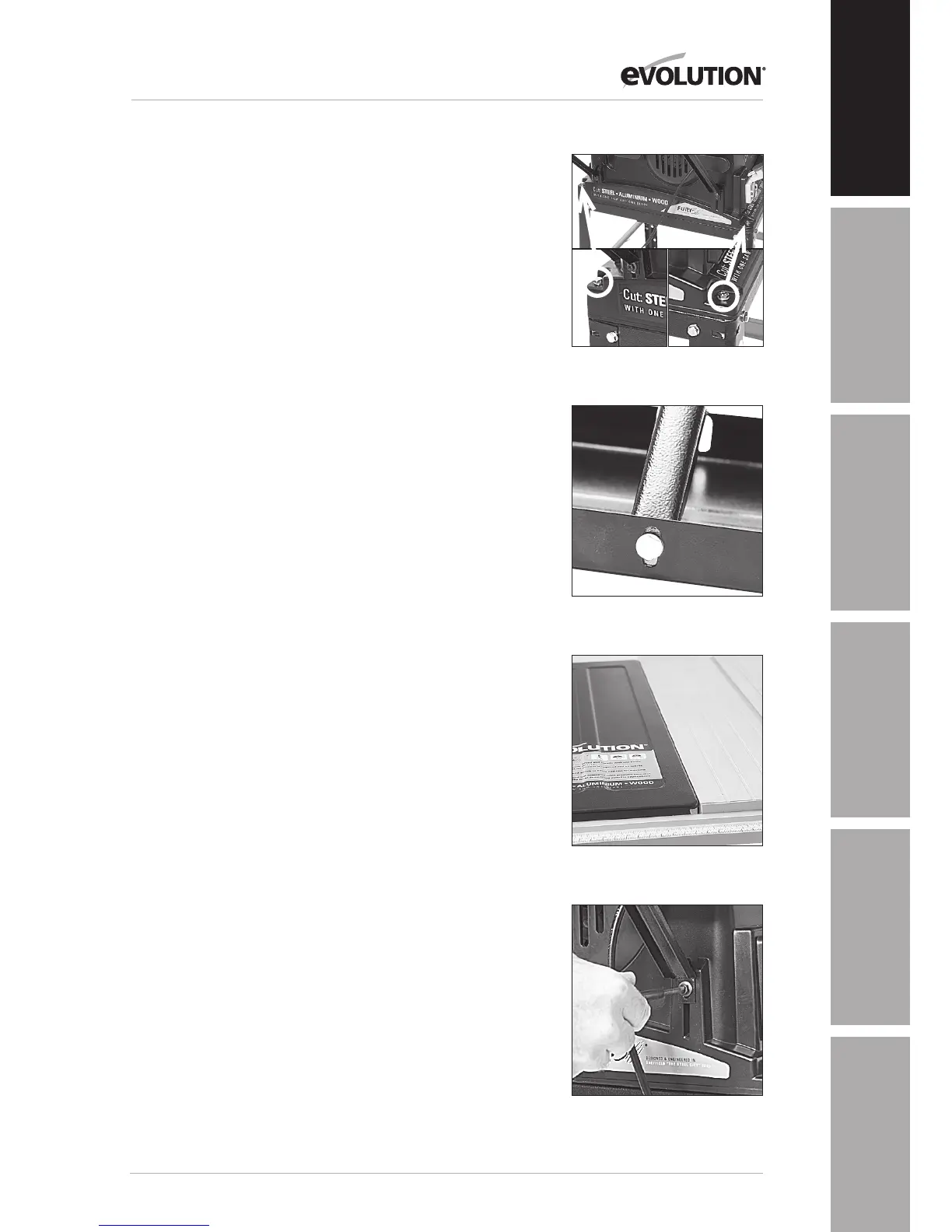
1. Attach the four bracing struts to the table extensions using
6mm hex bolts with a washer under the head of the bolt as well
as the nut. Position the front strut in the first slot. Position the
rear strut in the single slot to the rear of the extension. Tighten
both struts in the middle of their respective slots. See Fig 6.
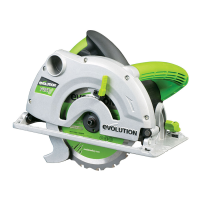
2. Captive nuts are incorporated into the RH and LH edges of
the table. Attach the table extensions (single hole to the front)
to the table top using the ø5mm socket headed screws and
washers.
3. Ensure that the saw table edge and extension table edge
are flush and level with each other. Tighten the ø5mm socket
screws. See Fig 7.
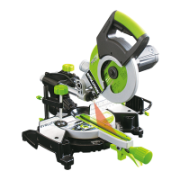
4. Using a straight edge or similar placed across the table and
extension to ensure alignment, position each bracing strut to its
body mounting turret. Use the hex headed self tapping screw
to secure each bracing strut to its turret. The screw will cut its
own thread into the turret slot. See Fig 8.
5. Final micro adjustment and alignment of the table
extensions is possible by repositioning the relevant fixing
screw in their slots.
Fig 5
Fig 6
Fig 7
Fig 8