14
www.evolutionpowertools.com
ASSEMBLY
To assemble this saw you will need: Cross head screwdriver, 8mm & 10mm spanner or socket wrench,
13mm Socket wrench, 5mm allen key and a rubber mallet.
Note: This process can be considerably aided by studying the images of the assembled machine and
the components found on the machine overview & what’s in the box pages. Unpack all components
including xings and familiarise yourself with them before attempting to assemble the machine. Enlist
competent help when assembling this machine. Use the rubber mallet to aid assembly.
THE BUILD PROCESS:
WARNING: This machine is heavy. Enlist competent help when moving or lifting this machine.
Step1
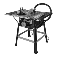
• Loosen the 4 bolts under the large table extension and slide the extension to line up with the end of the
rear slide rail. (Fig1)
• Ensure the table extension is in the closed position and adjust the front slide rail until the measuring
indicator reads 0.
• Check that the extension is level with the main table and secure all 4 bolts.
Step 2
• Turn the machine body upside down and place on a clean, secure surface. Ensure the blade adjustment
handle is facing you. (Fig 2)
• Attach the two components labelled 1 using xings D, E & F from BAG 2. (Fig 3)
NOTE: The raised end of component 1 should be to the left hand side of the machine.
• Fit the two domed end caps labelled K from BAG 4 into the raised end of component 1, and two of the
at end caps labelled J from BAG 4 into the opposite end.
Step 3
• Attach component 2 to component 3 using xings G & I from BAG 3. (Fig 4) Ensure component 2 is
inbetween the latch & component 3.
• Now attach component 4 to component 3 using xings A, B & C from BAG 1. Ensure that component 4
is the right way round so the latching pin engages with the latch on component 3. (Fig 5)
• Do not over tighten. Repeat this step on both sides.
• Fit two end caps labelled J from BAG 4 into the raised ends of component 3 and check that the pin
engages with the latch. (Fig 6)
Step 4
• Attach component 4 to the machine body, through component 1, using xings A, B & C from BAG 1.
Do not over tighten. (Fig 7)
NOTE: Ensure that the latching mechanism is on the same side as the blade adjustment handle.
• Repeat this step on both sides. (Fig 8)
Step 5
• Slide component 5 into the bottom of component 6 and secure using xings H & I from BAG 3 (Fig 9)
• Fit two end caps labelled J from BAG 4 into the open ends of component 6 ensuring that the slot in the
cap allows a bolt to pass through the holes.
Step 6
• Attach component 6 to the machine, through component 1, using xings A, B & C from BAG 1. (Fig 10)
NOTE: Ensure that component 5 is pointing down when attaching component 6 to the machine.
• Manoeuvre component 3 & 6 until the bolt holes line up. Fasten together using xings A, B & C from
BAG 1. (Fig 11)
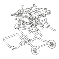
Step 7
• Attach the wheels (Component 7) into their service position on component 3 using xings M from BAG
4 (Fig 12).
• Do not over tighten and ensure the wheel spins freely.
• With help from a second person, turn the assembled saw onto its frame. The frame is now complete.
DID YOU KNOW?
We’ve made a handy assembly video that shows simple step by step
instructions to help you assemble your machine. Scan here or visit
www.evolutionpowertools.com/uk/build/tablesaws/assembly