18
www.evolutionpowertools.com
CHECKING/ADJUSTING THE RIP FENCE
When the Rip Fence has been attached to the machine, the Rip
Fence should be checked to ensure that it lies parallel to the blade.
• Raise the blade to its full height.
• Rest a straight-edge or similar against the blade.
• Bring the Rip Fence up to the straight-edge and
check for parallelism.
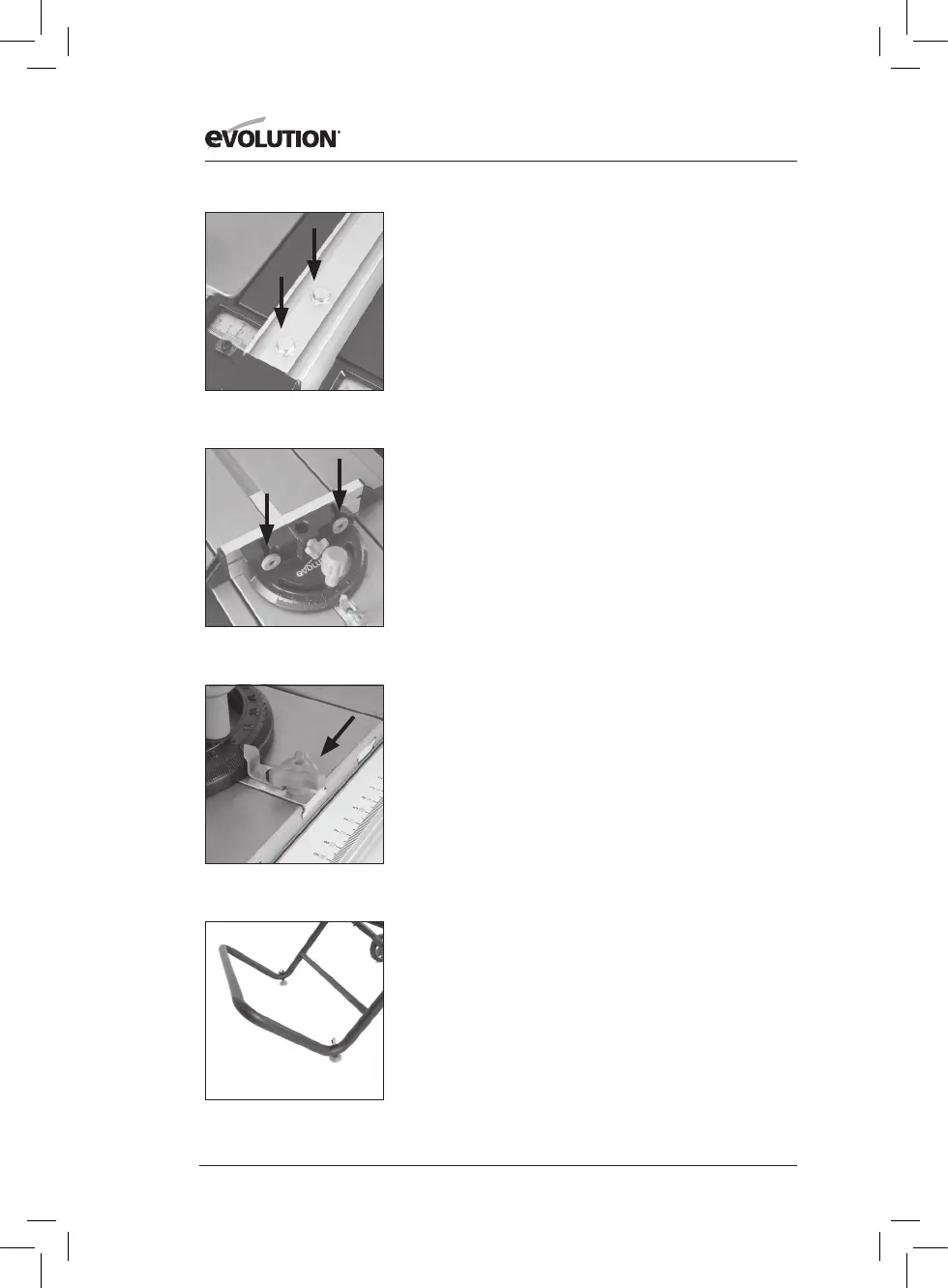
• If adjustment is needed, gain access to the two hex headed
screws located on the Rip Fence (Fig. 21).
• Loosen these screws slightly using a suitable wrench, and
adjust the fence as required.
• Tighten and re-check the Rip Fence when correct alignment
has been achieved.
• Lower the blade.
THE MITRE GAUGE
The Mitre Gauge labelled 9 has an adjustable Face Plate and
provision for a Hold Down Clamp labelled 10.
• Insert the Hold Down Clamp into the socket in the Mitre
Gauges main body and tighten the locking screw.
• Attach the Face Plate of the Mitre Gauge.
• Slide the attachment screws through the two (2) holes in
Mitre Gauges vertical face and secure in place with the
thumb nuts (Fig. 22).
• The Mitre Gauge is usually employed on the LH side of the
table and runs in an inverted T slot in the table top.
• The Mitre Gauge can be locked onto the Sliding Carriage by
screwing the locking screw into a hole located to the front
edge of the Sliding Carriage (Fig 23).
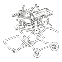
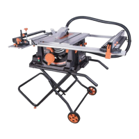
TRANSPORTING YOUR TABLE SAW
WARNING: Ensure that this procedure is only carried out with
the machine disconnected from the mains supply.
• Ensure that the machine is disconnected from the mains supply
and that the power cord is securely stored on the machine.
• Release the latching pin.
• Grasp the transportation handle (Fig. 24).
• Gently and slowly lift the handle, allowing the machine to
maintain balance and stability.
• Wheel the machine to its new location
.
Fig. 21
Fig. 22
Fig. 23
Fig. 24