page 14 of 49
The tables above can be used to determine the approximate voltage drop at peak currents
per phase. The installed length is the running distance from the source panel to the
charger (the table takes into account resistance in both legs of the circuit).
For single-phase chargers, the following table can be used to determine the maximum power an
existing circuit can provide, if there is no provision for a new installation:
Derating guideline for single-phase charger
* C-curve rating of circuit breaker
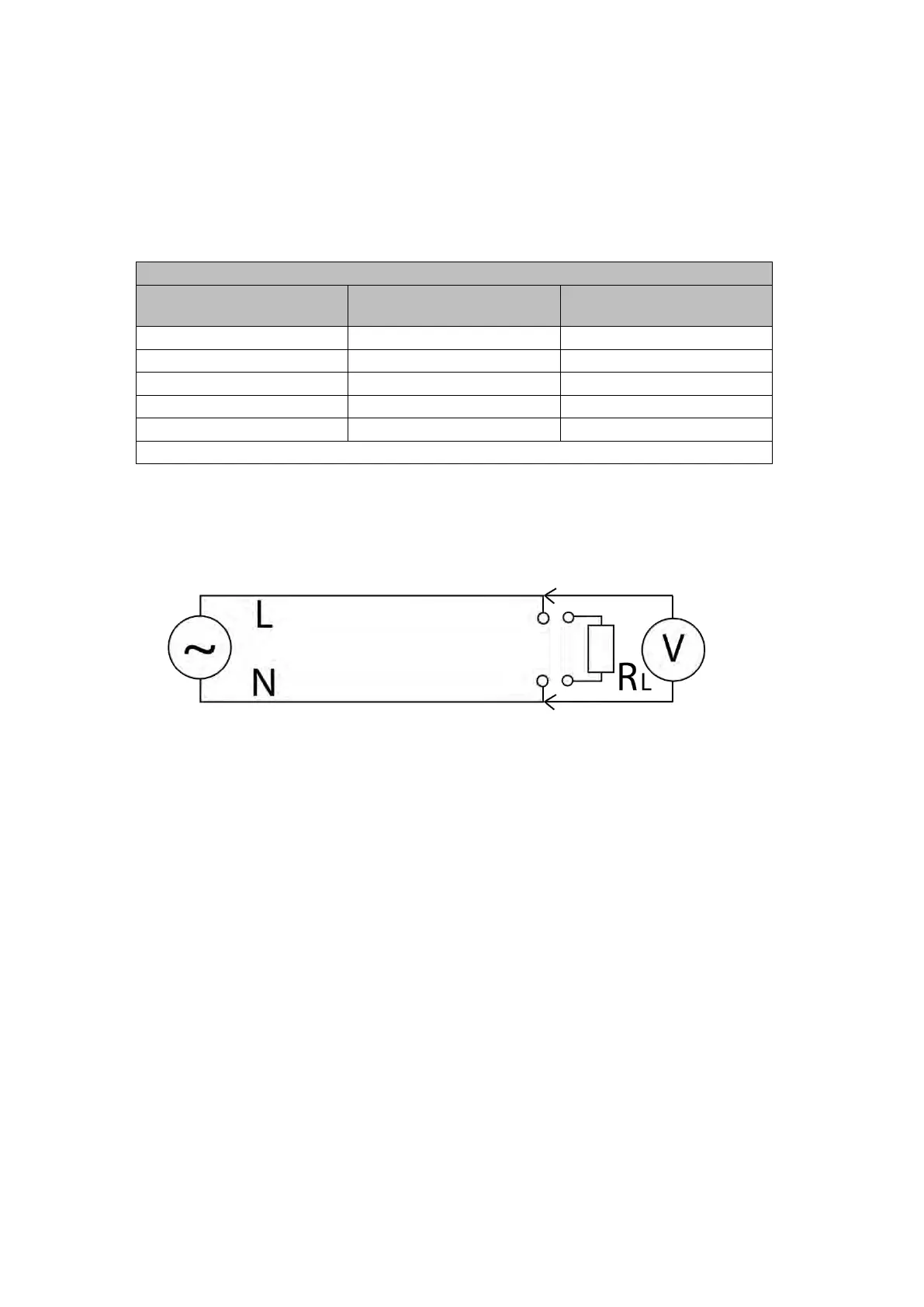
The circuit voltage drop at peak load can also be determined using a test load R
L
of lower
power rating. The voltage drop is calculated from the difference between the open-circuit and
loaded voltage at the circuit load side: Voltage drop = V
open-circuit
- V
Load
The nomograph below can be used to calculate the circuit voltage losses at peak current. For a
given test power load, a line can be drawn from the origin to the corresponding value on the
upper horizontal axis. Then, the measured voltage drop can be matched to the corresponding
peak current drop by reading out the left vertical axis. The nomograph includes sample plots for
1-4 kW test loads and assumes nominal 230V at which the test load is specified.
Experimental determination of voltage drop using a test load R
L
-
measurement