Do you have a question about the Excell 150S and is the answer not in the manual?
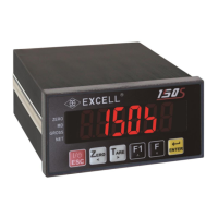
Details the front panel components, display, and indicators.
Describes the rear panel terminal block, calibration switch, and connectors.
Explains the function of each key on the instrument's keypad.
Details the A/D conversion, power supply, and other technical specifications.
Instructions on how to view the firmware version.
Provides physical dimensions and panel cutout information for the device.
Outlines the steps for setting up and operating various functions of the instrument.
Lists and explains common error messages encountered during general function settings.
Details the procedure for setting various function parameters using specific codes.
Details parameters and settings for various FNC functions like Digital Filter and Key Lock.
Explains how to set and manage the internal calibration password for the device.
Illustrates the proper connection diagram for the load cell to the instrument.
Provides a flowchart for parameter setting and the calibration process.
Illustrates the step-by-step process for initiating different calibration modes.
Details the procedure for calibrating the instrument using the MODBUS communication protocol.
Outlines the steps for performing specification calibration, including parameter codes.
Describes the step-by-step process for performing general calibration of the instrument.
Explains the procedure for calibrating the linearity of the instrument across multiple points.
Shows how to view the current settings for linearity calibration.
Details how to clear the existing linearity calibration settings.
Guides through the digital calibration process, including zero and span voltage setup.
Lists and explains the various function configuration codes for weight comparison.
Provides a detailed guide to functional parameters like Batching mode and delay times.
Details how to configure check weighing parameters like Final, SP1, SP2, and Free Fall values.
Describes the output conditions for normal batching, loss-in-weight, and Hi/OK/Lo signals.
Illustrates the flowchart for the normal batching operation when SQ-01 is set to 1.
Depicts the flowchart for the loss-in-weight operation when SQ1 is set to 2.
Shows the flowchart for Hi, OK, Lo output logic based on various settings.
Provides the flowchart for normal batching with the built-in program for SQ-01=4.
Presents the flowchart for loss-in-weight with the built-in program for SQ-01=5.
Explains the different hold modes, including general and peak hold operations.
Details the flowchart for hold mode operations based on various function settings.
Describes the Hi, OK, Lo comparison outputs for different hold modes.
Explains how automatic totalizing and data transmission work with different batching modes.
Details pin configuration, settings, and types (RS-232/485/422) for serial interfaces.
Explains data formats, comparison conditions, and command structures for interface communication.
Covers pin locations, circuits, and function settings for BCD parallel output.
Details location, connections, adjustments, and function settings for analogue output.
Describes pinouts, configurations, input/output signals, and circuits for parallel interfaces (OP-04, OP-05).
Guides on how to restore all instrument parameters to their factory default settings.
Details how to access and use maintenance functions for system checks and adjustments.
Explains how to enter and use the test mode for checking hardware components.
| Brand | Excell |
|---|---|
| Model | 150S |
| Category | Controller |
| Language | English |