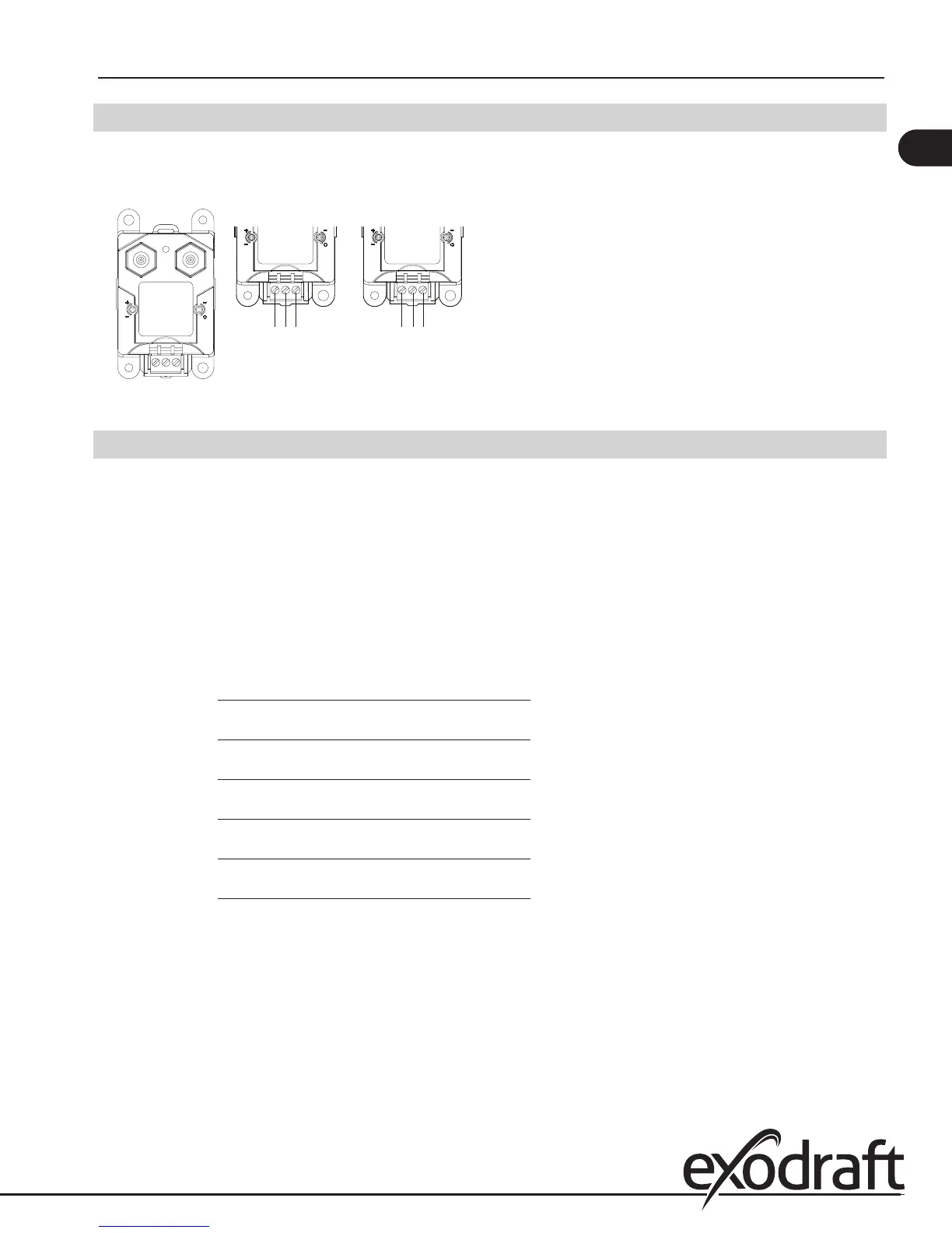
4.4 Wiring of Ashcroft XTP sensor
The Ashcroft XTP sensor is wired as shown below. The wiring to the Ashcroft XTP sensor is always the same, while the wir-
ing on the EBC30 control depends on whether it is to be wired for exhaust or intake operation:
Fig. 13
40 41 39
48
49
47
POWER
HI LO
SPAN
ZERO
SPAN
ZERO
Exhaust Intake
SPAN
ZERO
4.5 Wiring of the control for priority operation
The control features priority operation, which is used only in case of a power failure or mechanical failure at the fan loca-
tion. The feature will automatically evaluate if one or more appliance(s) can operate safely without mechanical draft. This
function is constantly monitored by the PDS function and only if the min. draft point is satised, will operation be allowed.
On a call for heat, the control will rst probe the appliance connected to the AUX1 input/AUX1 relay terminals, secondly
the appliance connected to the AUX2 input/AUX2 relay terminals and so on. Consider the operating priority of the appli-
ances when wiring to the control.
List appliance priority here:
Priority Appliance type or number Connects to terminals
1 AUX1 - input/relay
2 AUX2 - input/relay
3 AUX3 - input/relay
4 AUX4 - input/relay
5 AUX5 - input/relay
6 AUX6 - input/relay
In case the highest priority appliance is not operating and a low priority appliance calls for heat, the control will allow the
low priority appliance to operate.
11
EBC30 3002180 100315