Continuous operation
For continuous operation, Dip Switch 1 & 2 on the back of the display card on the EBC30 door must be in the up/on posi-
tion. AUX INPUT connections are not used since the Control always attempts to maintain the pressure set point regardless
of appliance status. The AUX INPUT LEDs remain lit in Continuous operation and all other EBC30 functions remain the
same as in Intermittent Operation.
5.2 Pre-operation inspection
After mounting and wiring has been completed, check the control for the following items before applying power:
• check for wiring errors
• verify that there are no wiring chips, screws, etc. remaining inside the controller
• check that all screws and terminal connections are tight
• verify that no exposed wire ends are touching other terminals.
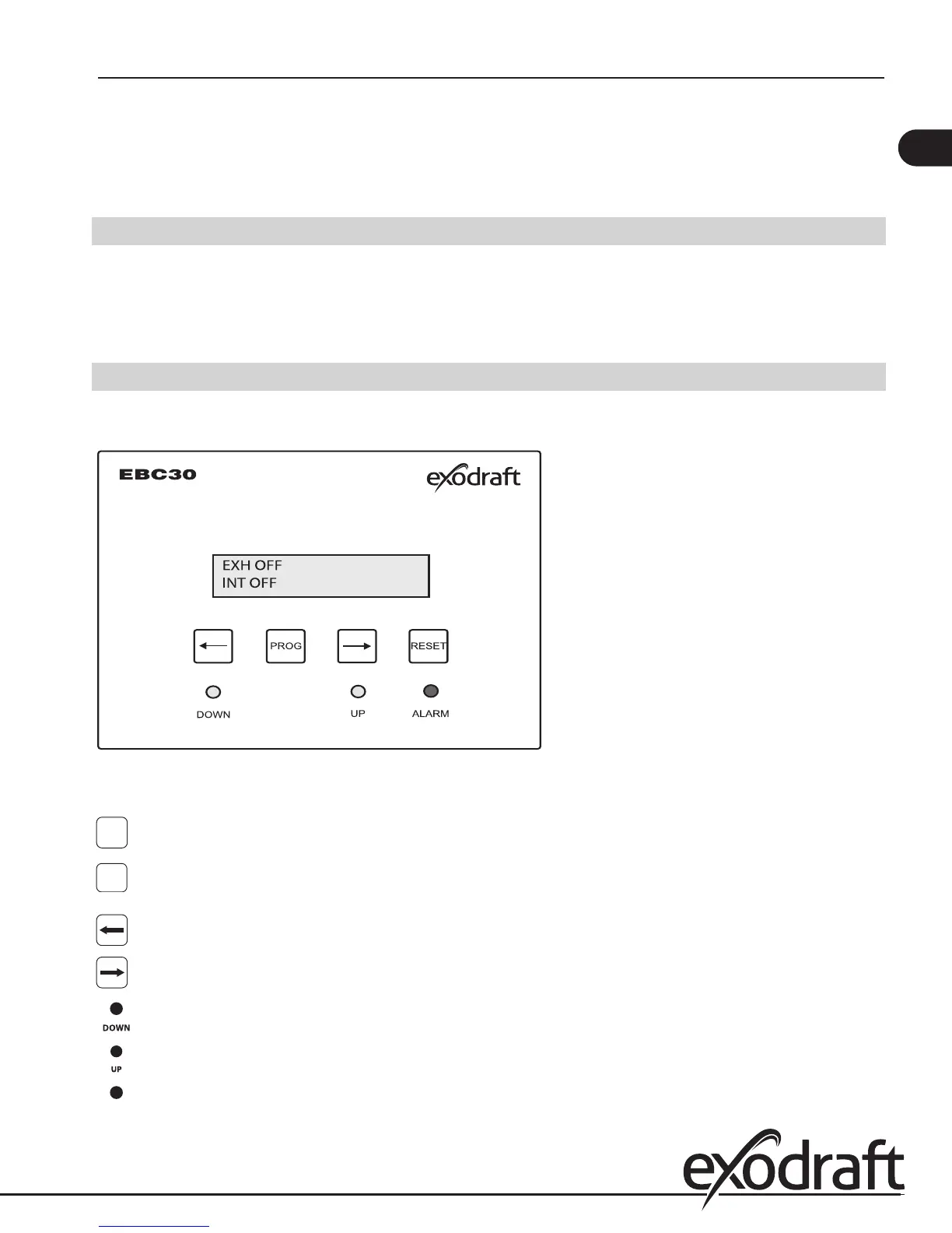
5.3 Key panel identication and operation
When AC power is applied to the control, the keypad panel display will show the following:
Fig. 13
The keypad part names and functions are:
PROG
PROGRAM KEY. Used to access the menu - press for 3 seconds to get to the Quick-menu.
RESET KEY. Key used for resetting control and fault codes. Also used to accept programming
changes and exit the programming mode.
DOWN KEY. Used to decrease the value of a parameter.
UP KEY. Used to increase the value of a parameter.
DECELERATION INDICATOR. When yellow light is lit, it indicates decreasing fan speed.
ACCELERATION INDICATOR. When yellow light is lit, it indicates increasing fan speed.
ALARM INDICATOR. When red light is lit, it indicates an error that must be corrected.
RESET
13
EBC30 3002180 100315