4. Electrical installation
4.1 General
DANGER
Turn o electrical power before servicing. Contact with live electric components can cause shock or
death.
NOTE
EBC30 is designed for 1 x 120 V AC power supply only. Fan output is regulating on the neutral side and can-
not be connected to other circuits.
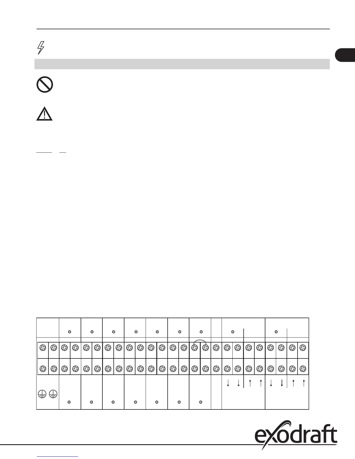
The terminals are connected as shown (for additional information go to chapter 5.1):
Terminal Use
1 Power Supply-L1 (Phase)
2 Power Supply-N (Neutral)
3, 4 Ground
5, 6 AUX1 Dry Contact (Normally Open)
Output to Appliance 1 (0-250 V, 8 A)
7 AUX1 Input - Boiler 1 Thermostat Input
10-250 V AC/DC (Load, Pos.)
8 AUX1 Input - Boiler 1 Thermostat Input
(Common, Neg.)
9, 10 AUX2 Dry Contact (Normally Open)
Output to Appliance 2 (0-250 V, 8 A)
11 AUX2 Input - Boiler 2 Thermostat Input
10-250 V AC/DC (Load, Pos.)
12 AUX2 Input - Boiler 2 Thermostat Input
(Common, Neg.)
13, 14 AUX3 Dry Contact (Normally Open)
Output to Appliance 3 (0-250 V, 8 A)
15 AUX3 input - Boiler 3 Thermostat Input
10-250 V AC/DC (Load, Pos.)
16 AUX3 Input - Boiler 3 Thermostat Input
(Common, Neg.)
17, 18 AUX4 Dry Contact (Normally Open)
Output to Appliance 4 (0-250 V, 8 A)
19 AUX4 Input - Boiler 4 Thermostat Input
10-250 V AC/DC (Load, Pos.)
20 AUX4 Input - Boiler 4 Thermostat Input
(Common, Neg.)
21, 22 AUX5 Dry Contact (Normally Open)
Output to Appliance 5 (0-250 V, 8 A)
23 AUX5 Input - Boiler 5 Thermostat Input
10-250 V AC/DC (Load, Pos.)
24 AUX5 Input - Boiler 5 Thermostat Input
(Common, Neg.)
25,26 AUX6 Dry Contact (Normally Open)
Output to Appliance 6 (0-250 V, 8 A)
27 AUX6 Input - Boiler 6 Thermostat Input
10-250 V AC/DC (Load, Pos.)
28 AUX6 Input - Boiler 6 Thermostat Input
(Common, Neg.)
29 Draft Input - Supply to EXTERN AL switch (24 V DC)
30 Draft Input - Return from EXTERN AL switch (24 V DC)
31 Override Input - (positive) - 0-250 V AC/DC
32 Override Input - (common)
33, 34 Alarm Relay - Dry Contact (Normally Open)
Close on Alarm Condition, (0-250 V AC, 8 A)
35, 36 VFD1 Relay - Dry Contact (Normally Open)
for Exhaust (0-250 V)
37 Output to Exhaust VFD1 - (positive) 0-10 V
38 Output to Exhaust VFD1 - (common)
39 Power Supply to Exhaust Transducer
(positive) - 24 V DC
40, 42 Output to Exhaust Transducer - (common)
41 Input from Exhaust Transducer - (positive) 0-10 V
43, 44 VFD2 Relay - Dry Contact (Normally Open) for Intake (0-250 V)
45 Output to Intake VFD - (positive) 0-10 V
46 Output to Intake VFD - (common)
47 Power Supply to Intake Transducer (positive) - 24 V DC
48, 50 Output to Intake Transducer - (common)
49 Output to Intake Transducer - (positive) 0-10 V
Fig. 9
3 4 7 8 11 12 15 16 19 20 23 24 27 28 31 32 34 37 38 41 42 45 46 49
0
1 2 5 6 9 10 13 14 17 18 21 22 25 26
29 30 33 35 36 39 40 43 44 47 48
AUX1
RELAY
AUX2
RELAY
AUX3
RELAY
AUX4
RELAY
AUX5
RELAY
AUX6
RELAY
DRAFT
INPUT
ALARM
RELAY
SUPPLY
120VAC
60Hz
L1 N
+24VDC
0VDC
VFD 1
RELAY
VFD 2
RELAY
+24VDC
0VDC
AUX1
INPUT
AUX2
INPUT
AUX3
INPUT
AUX4
INPUT
AUX5
INPUT
AUX6
INPUT
OVERRIDE
INPUT
ALARM
RELAY
0-10V
0VDC
0-10V
0VDC
0-10V
0VDC
0-10V
0VDC
VFD1 XTP1
EXHAUST
VFD2 XTP2
INTAKE
+ - + - + - + - + - + - + -
9
EBC30 3002180 100315