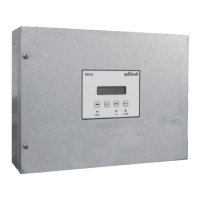
6. Maintenance and troubleshooting
Most terminal connections are monitored for proper operation. LED lights indicate operating status. If a light is lit, it indi-
cates everything is functioning properly while a light out indicates a problem on the circuit it monitors. In addition, fault
codes are shown on the display.
The fault codes are:
Display Explanation
A1 Draft Exhaust Insucient draft pressure. Can be caused by:
1. Chimney fan does not have enough capacity
2. Mechanical or electrical fan failure
3. Blocked chimney
4. Introduction of excessive dilution air
5. XTP sensor not responding correctly
A2 Draft Intake Insucient intake air supply. Can be caused by:
1. Supply fan does not have enough capacity
2. Mechanical or electrical fan failure
3. Blocked air inlet our louver
4. Excessive exhaust from exhaust fans located in mechanical room
A3 Power Fault Indicates there has been a power fault
A4 XTP-Exhaust Indicates a disconnected signal from the XTP-Sensor on the exhaust side to the control Can be
caused by:
1. Loose connections
2. Faulty XTP-sensor
3. Faulty controller
A5 XTP-Intake Indicates a disconnected signal from the XTP-sensor on the intake side to the control. Can be
caused by:
4. Loose connections
5. Faulty XTP-Sensor
6. Faulty controller
A6 Error Start
Indicates that the control has not been able to release the heating appliance(s) within 15 min-
utes.
A7 Alarm Override Indicates alarm has been ignored
A8 Draft Input Missing signal from PDS-function. Indicates a faulty function.
Other fault possibilities are shown below:
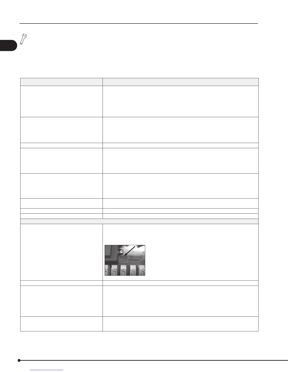
Red alarm on main board is lit Indicates a malfunction. Can be caused by:
1. No communication between main board and display.
Make sure the cable is connected. This error will shut down the appliances within 20 seconds.
Red alarm diode ashes Indicates the control operates the appliances in prioritized mode.
Yellow light (UP) is lit continuously
Indicates the control is accelerating the fan speed. If it stays on constantly it indicates a system
fault. This can be caused by
1. Wiring problems
2. A clogged tube or probe
3. A leaking chimney system
4. Inadequate fan capacity
Yellow light (DOWN) is lit continuously Indicates a malfunction. Can be caused by:
1. If a Triac Board is installed this is an indication that the neutral connection is shared with other
equipment. It must be a dedicated line between the control and the fan.
18
EBC30 3002180 100315