380926 4.1 07/07
5
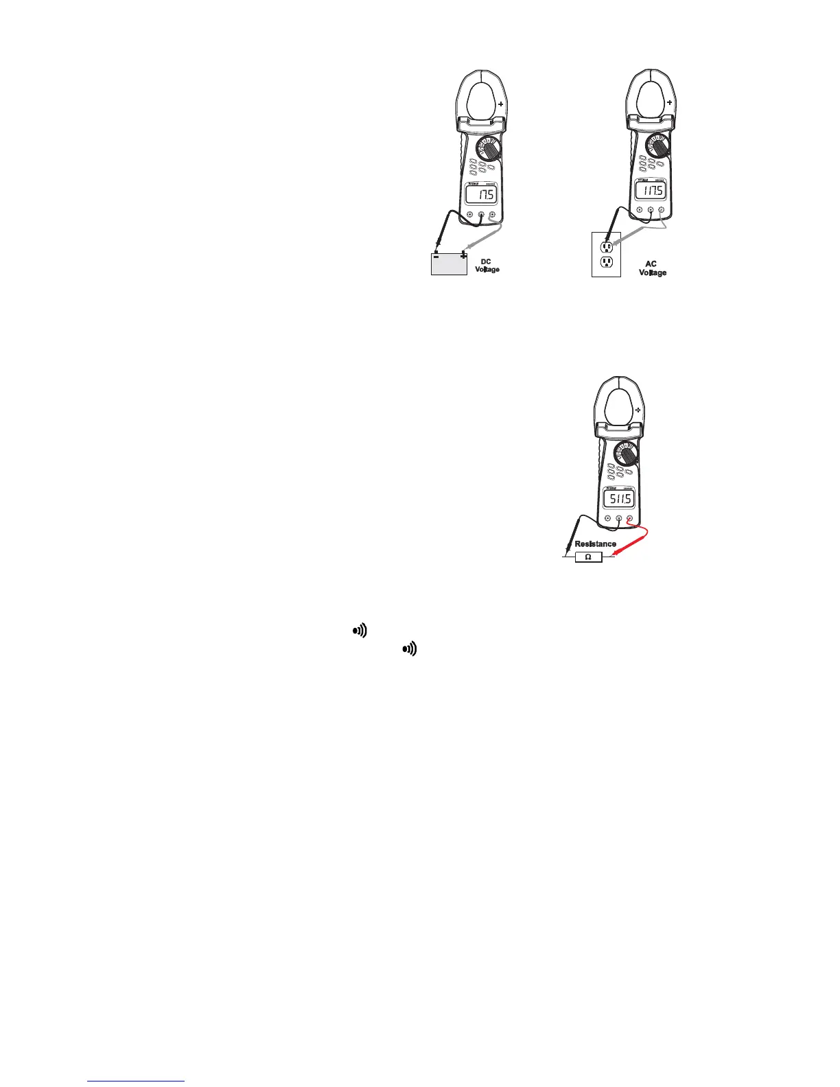
Voltage Measurements, DC/AC
1. Set the Function Switch to the V
position.
2. Press the FUNC key to select AC or DC.
3. Insert the black test lead to the COM
input jack and the red test lead into the
V input jack.
4. Connect the test leads in PARALLEL
with the circuit to be measured (see
diagrams).
5. Read the measured value from the LCD
display.
Resistance Measurements
CAUTION: Before taking any in-circuit resistance measurements
remove power from the circuit under test and discharge all
capacitors.
1. Set the Function switch to the Ω position.
2. Press the FUNC key until the ohms symbol appears on LCD.
3. Insert the black test lead to the COM input jack and the red
test lead to the Ω input jack.
4. Connect test leads to the device under test (see diagram).
5. Read the measured value from the LCD display.
Continuity Test
1. Set the Function switch to the position.
2. Press the FUNC key until the "Ω" and " " symbols appear on the display.
3. Insert the black test lead to the COM input jack and the red test lead to the Ω input
jack.
4. Connect the test lead tips to the device to be measured (refer to diagram for
resistance measurements above).
5. Read the measured value from the LCD display.
6. If the resistance is < 10Ω approx. an audible signal will be heard.
www.burntec.com