MAX300-RTG: Installation Manual Hardware Installation
30
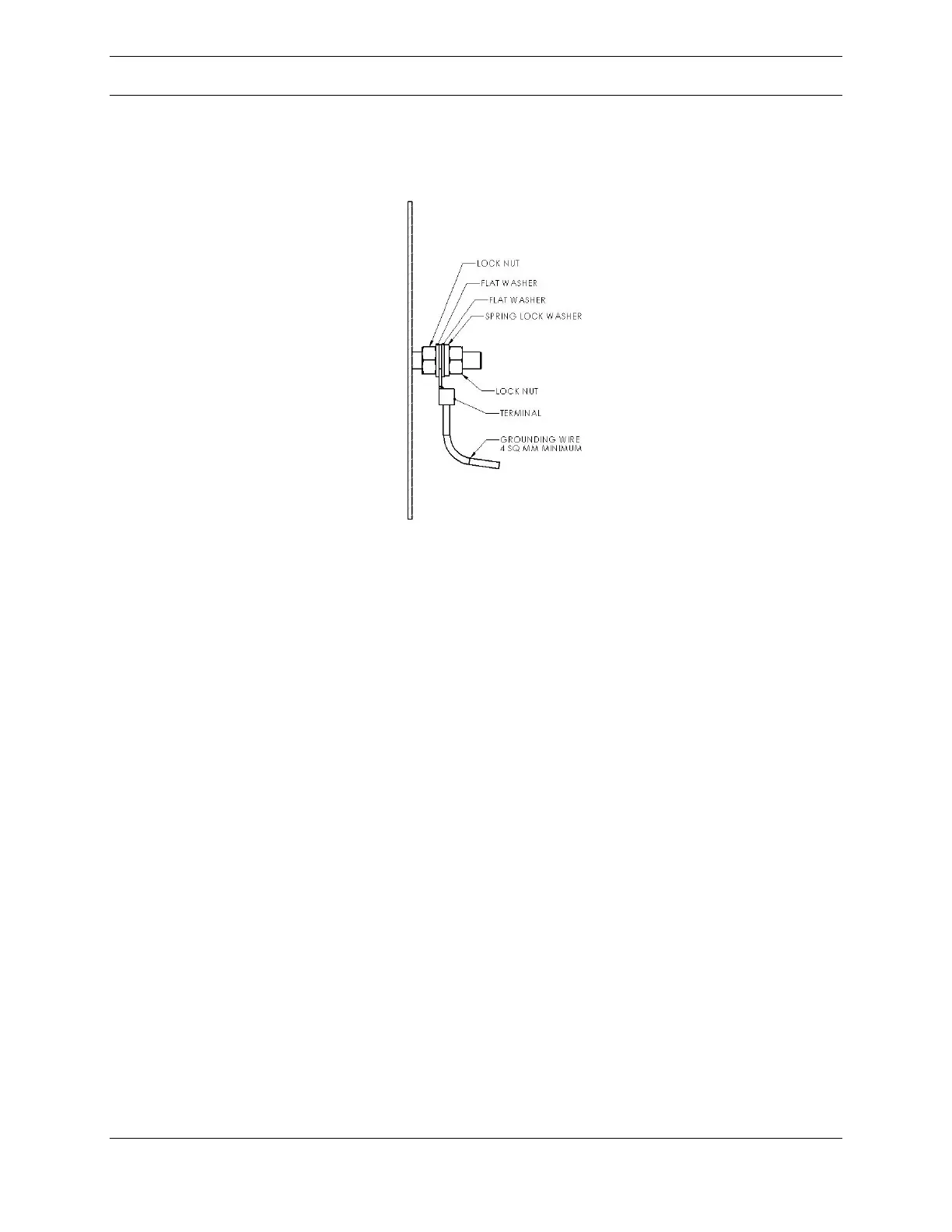
Figure 12: Earth connection diagram
Earthing
An earth connection point is provided on the external surface of the pressurized
enclosure, and on the external communication disconnect box option. Refer to
figures 1 through 6. These connections must be used to join the instrument’s
metalwork to the earth-ground plane. The external earth wire must be protected so
that it cannot become accidentally loosened or damaged by twisting. It must be
sized in accordance with local rules for electrical installations and must not be
smaller in area than 4 square millimeters (7894 circular mils).
The purpose of these connections is to direct any electrical current, internally or
externally generated, into an external ground rod that will eliminate or minimize
any damage to personnel and equipment. In order to achieve the redirection of
current, the resistance between the earth-ground connection and the external
earth-ground lug must be kept below 0.1 ohms. The hardware shown in Figure 12
is supplied with the unit.