MAX300-RTG : Hardware Manual Hardware Maintenance
64
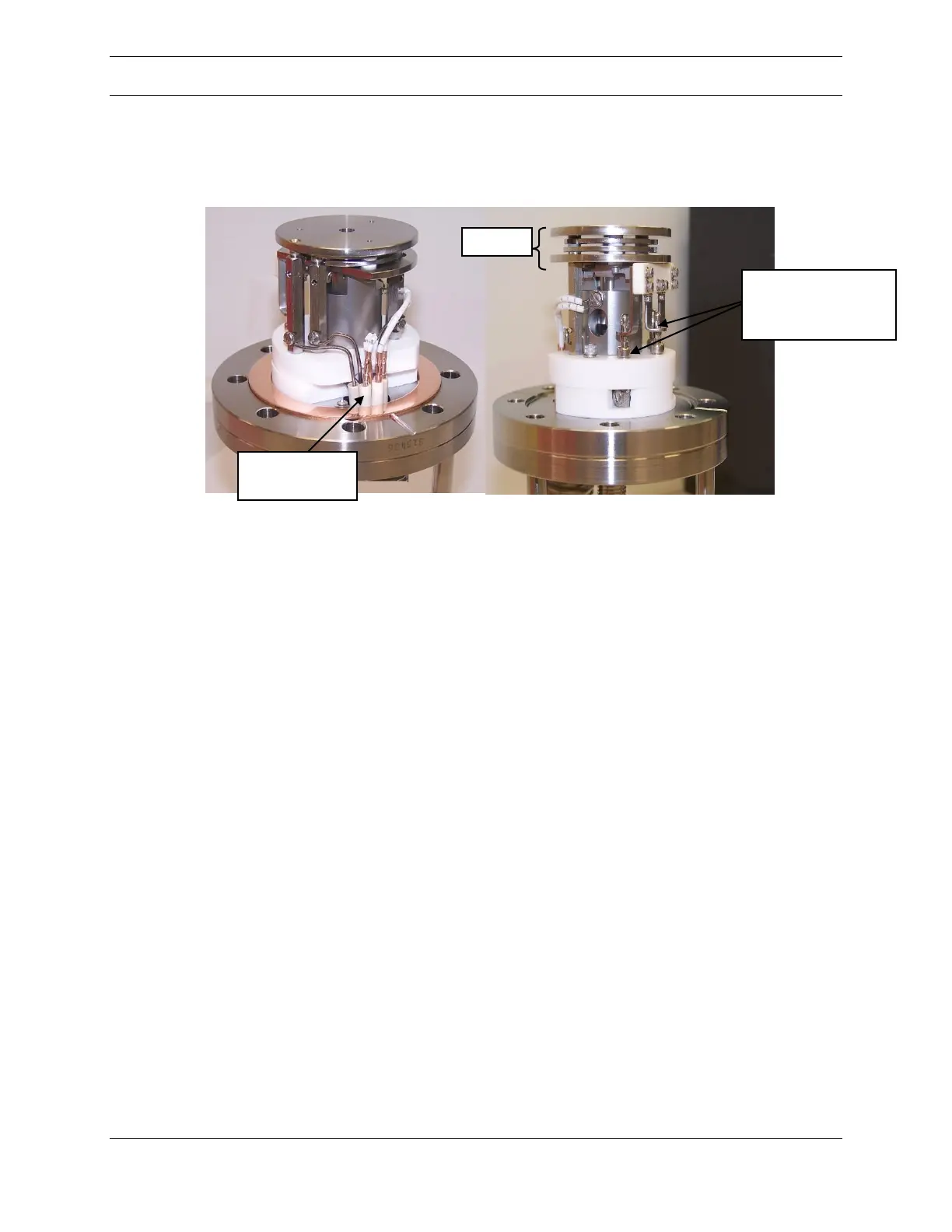
The ionizer assembly used in the MAX300-RTG has been designed for easy
installation and servicing. Figure 37 below depicts the ionizer assembly mounted
on the flange.
Figure 37: Ionizer Assembly Mounted on Flange
Tungsten or Yttria coated Iridium are available as the filament material. Two
filaments are present in the assembly, located on each side of the ion volume. Only
one filament is used at a time. When Filament 1 has reached the end of its useful
life, Filament 2 will automatically be put into effect. However, the system will NOT
transition automatically from Filament 2 to Filament 1. If both filaments have
burned out, the entire ionizer assembly must be replaced.
Note: Because the ionizer may be hot and remain hot for several hours in a vacuum
situation, caution should be taken when removing the ionizer assembly from the
vacuum chamber.
Changing the Ionizer Assembly
The first step in changing the ionizer assembly is to vent the vacuum system.
Following this, disconnect the ionizer connection cable and remove the inlet. It may
be convenient (though not required) to remove the ionizer’s inlet tube by loosening
the large central fitting on the ionizer flange, Figures 38 and 39 below. The hex
closest to the flange (5/8 inch) is welded on. The outer hex nut (3/4 inch) can be
rotated counter clockwise to loosen the fitting and remove the inlet. Be careful
when loosening this fitting that the wrenches do not contact the ten pin vacuum
feedthrough and damage it. Set the inlet aside where it will stay clean.
Ionizer’s
connection to the
flange.