MAX300-RTG: Installation Manual Hardware Installation
46
Analog Inputs: 4-20mA
Analog Outputs: 4-20mA
Digital Inputs: 24VDC
Relay Outputs: Contact ratings vary with the module installed
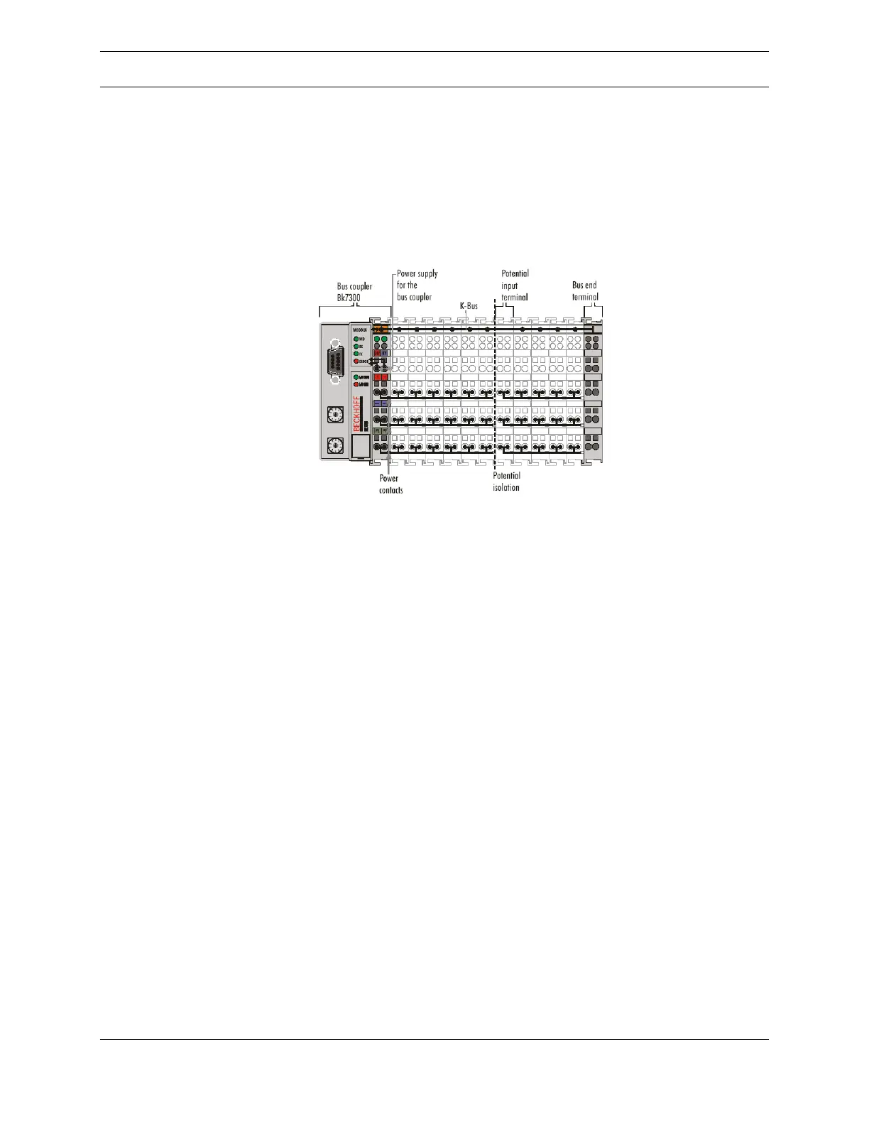
Figure 21: Bus Coupler
The BK7300 in Figure 21 connects the server PC with the electronic terminal
blocks. Modules can be added in any combination meeting the user’s needs. There
is a physical limitation within the MAX300-RTG enclosure of twenty-eight modules.
One unit consists of one Bus Coupler, any number of (1 to 64 modules) terminals,
and one end terminal. The communication to the Bus Coupler is via Modbus. The
analyzer controller acts as the Modbus Master, and the Bus Coupler acts as a
Modbus Slave.
4-20mA Analog Inputs and Outputs
The 4-20mA communications option is used to send or receive data over a loop of
wire where the current in the loop is proportional to the signal being transmitted.
This mode of communications is most often used over long distances, in an
environment that might otherwise induce electrical noise in the cable. Data is
scaled so that 4mA represents zero and 20mA represents full scale. The MAX300-
RTG software is capable of using this method to transmit data and instrument
parameters to external monitors or controllers. The software can also use this
method to receive parameters or instructions from an external source.
Each 4-20mA loop is known as a channel and can be configured separately. The
default conversion of digital to analog (or analog to digital) data divides the 4-20mA
range into discreet data steps where zero will correspond to 4mA and 4095 will