MAX300-RTG : Hardware Manual Hardware Maintenance
68
Note: When handling any clean vacuum chamber components, lint free or nylon
gloves must be worn.
Note: The following procedure needs to be read in its entirety before attempting to
remove the quadrupole assembly.
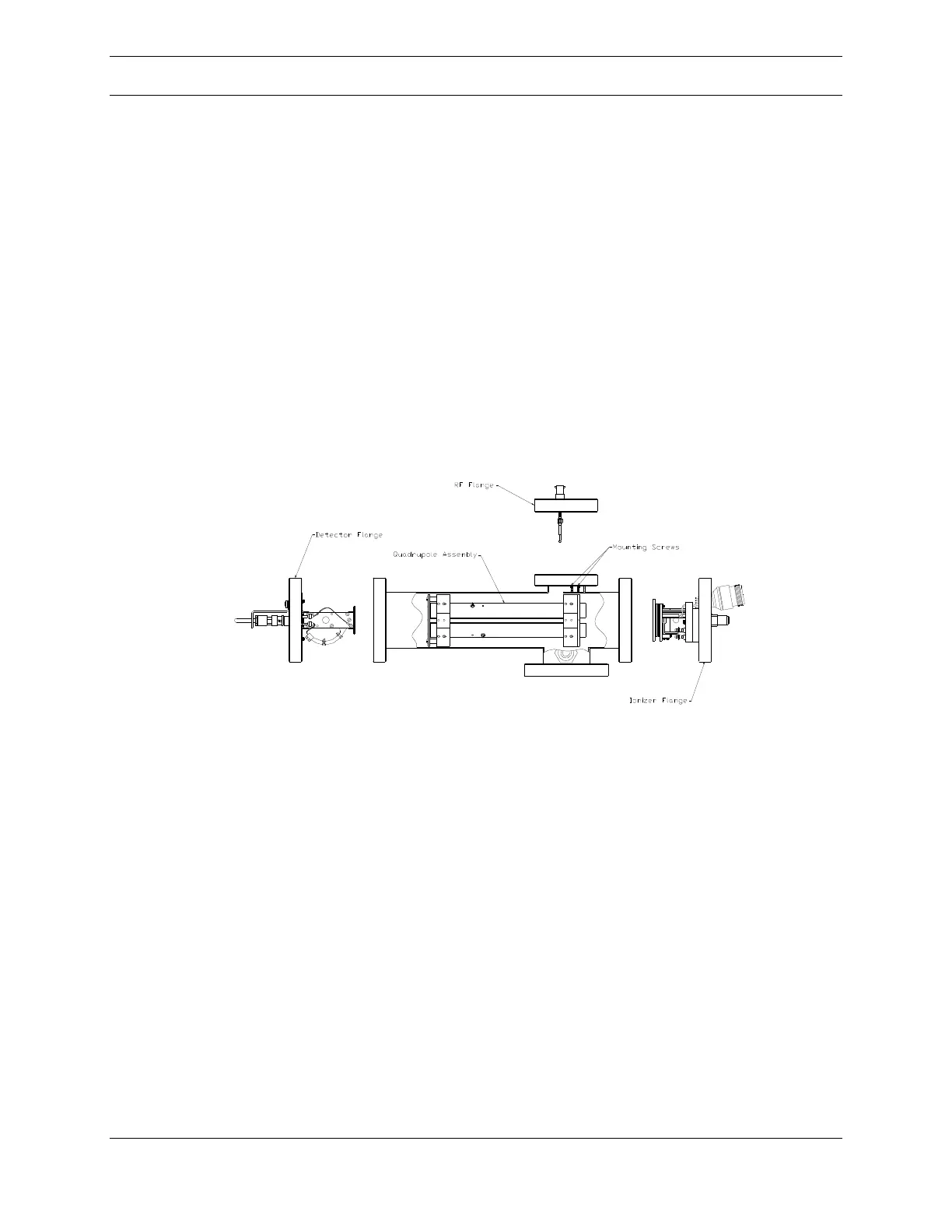
Before removing the quadrupole, the vacuum system must be vented. Slide the
VacTrac assembly out of the enclosure by disconnecting the inlet line from the
enclosure wall and releasing the slide latch on the left slide of the VacTrac
assembly. Disconnect the RF cables from the feedthrough flange on the top of the
vacuum chamber shown in Figure 42, below, by pushing down, rotating ~1/4 turn
counterclockwise, and then pulling. The RF connection flange assembly can then
be detached from the vacuum chamber (1/4 inch hex key).
Figure 42: Quad Assembly and Vacuum Chamber
The quadrupole can be removed from either the ionizer end or detector end of the
vacuum chamber. The detector end is nearest the wires that connect opposite
poles. If the ionizer has also been removed for routine maintenance, the
quadrupole can be pulled out the front of the chamber. If not, the assembly may
be removed from the rear by detaching the detector mounting flange. In both
cases, a 1/4 inch hex key is required.