MAX300-RTG : Hardware Manual Hardware Maintenance
73
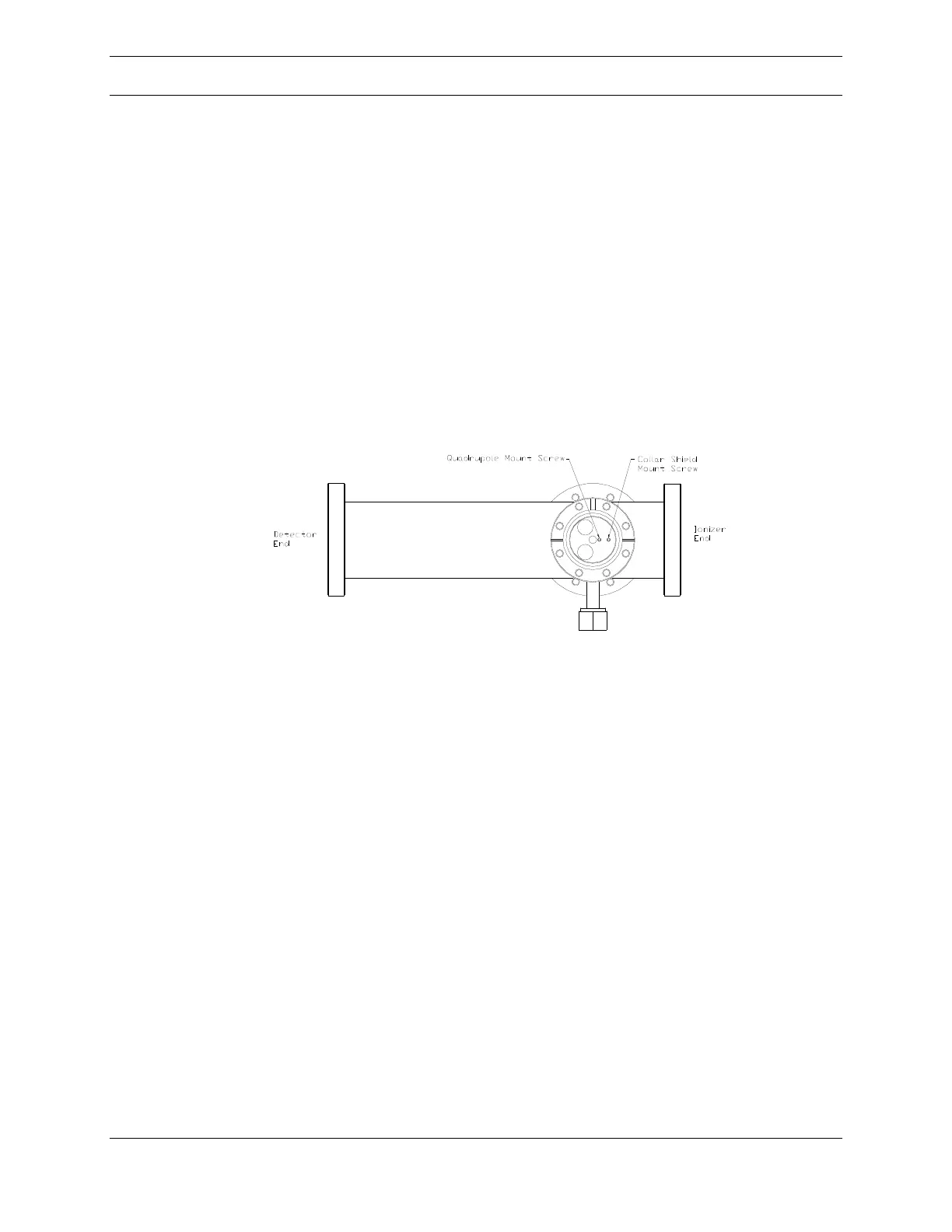
As noted previously, the quadrupole is secured within the vacuum system by two
screws. One screw engages the ceramic mounting collar and one threads into the
collar shield rod assembly. The quad assembly must be slid far enough into the
chamber so the holes in the chamber for these screws line up with the matching
holes in the quad assembly. This can be observed by looking into the RF
connection flange mounting port on top of the vacuum system.
A bird’s eye view depicting the location of these holes is shown in Figure 47 below.
Two 2-56 socket head screws with lock washers and the 5/64 inch hex wrench is
needed to secure the assembly.
Figure 47: RF Connection Flange – Bird’s Eye View
The RF connection flange assembly should then be installed onto the vacuum
chamber with a new 3-3/8 inch copper gasket. The spring loaded contacts of the
RF connection flange must make contact with the quadrupole rods, not the collar
shield end plate or chamber. The vacuum feedthroughs on this flange, when
properly installed, are offset toward the detector end of the chamber. Initially leave
these screws finger tight.
Use the ohmmeter to check the continuity between the feedthrough contacts on
the flange and the quadrupole rods and check for shorts to the chamber. Either the
ionizer or the detector flange will have to be removed to accomplish this. Once
verified that the electrical connections are correct, finish tightening the RF flange
screws. The securing socket head screws (1/4" hex key) should be tightened in a
crossing pattern that keeps the flanges parallel to each other.
If the ionizer mounting flange was removed, it should be re-installed using a new
4-1/2 inch copper gasket. The securing socket head screws will require a 1/4 inch