MAX300-RTG : Hardware Manual Hardware Maintenance
78
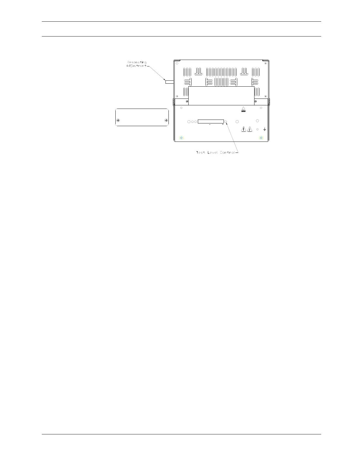
Figure 51: Quadrupole Controller (QC)
Note: The area must be non-hazardous for this procedure to be performed.
Using the controlling software, set the instrument to scan some small mass window
(10 amu) in the range where the instrument is most often used.
To resonate the QC:
Remove the access plate from the front of the QC labeled Resonating and
Calibration
Locate the switch on the front of the QC labeled Test – Operate and place
it in the Test position
Connect the voltmeter to the test points on either side of the switch. The
positive lead connected to the right test point and the negative lead to the
left one. The scale should be zero to 10VDC.
Use a small screwdriver to rotate the control labeled Test Level to the full
clockwise position
The voltmeter should now show an indication of a few volts
Using a flat blade screwdriver, slowly turn the Lucite rod (resonating
adjustment) located on the side of the QC using a flat blade screwdriver
until the indication on the voltmeter is maximized
Disconnect the voltmeter
Return the Test Level control to its full counter clockwise position
Return the Test – Operate switch to the Operate position
Install the access panel on the front of the QC
Note: Be sure not to turn the Lucite rod a full turn. The slit in the rod should be
approximately 45 from vertical.
LINEARIZE
OFFSET
FINE
ADJUST
CALIBRATE
MASS POSITION
OPERATE
TEST
TEST
LEVEL
OSCILLATOR
STATUS
Extrel
RESONATING AND CALIBRATION
ACCESS PANEL