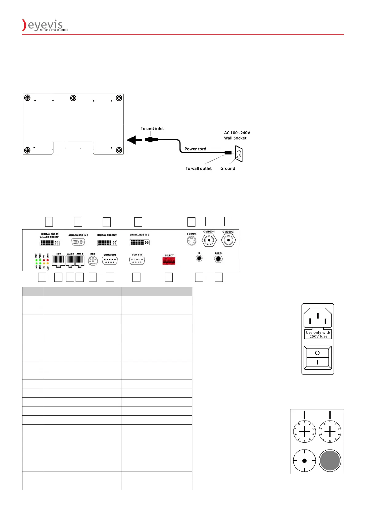
EYE-LCD4600M/W-SN 17
2.5 Input Source Connections
No. Name Remarks
1 Digital/ Analog RGB In 1 DVI-I
2 Analog RGB In 2 HD15
3 Digital RGB Out DVI-I
4 Digital RGB In 2 DVI-I
5 S-Video Mini-DIN 4pol
6 C-Video 1 BNC
7 C-Video 2 BNC
8 Status LEDs
9 NETWORK RJ45
10 AUX 2 RJ45
11 AUX 1 RJ45
12 Keyboard PS/2
13 COM 2 Out D-Sub 9pin
14 COM 1 In D-Sub 9pin
15 DIP Switches
1. Force Address 1
2. Disable the Watchdog reset function
and replace by a soft reset
3. Enable verbose Error Output
4. Suppress trunking of Error Output if
many error messages occur
5. Erase database on start
6. Service: Flash Scaler Firmware
16 IR Mini Jack 2.5mm
17 AUX 3 Mini Jack 3.5mm
1. Mains Connection
2. Main Fuse
Use only 5A fuse (C-
class)
3. Main Power ON/OFF
Switch with integrated
5A fuse (C-Class)
1. Addressing
Turn-switches for setting
the display address
left switch -> 0...90
right switch -> 0...9
Example:
display address is 16:
left switch -> 1
right switch -> 6
2. Push for Auto Source
Scan
3. Standby ON/OFF
1.
3.2.
1.
2.
3.
1 2
3
4 5
6 7
8
9 10 11 12 13 14 15 16 17
3 AC power cord connection
3 Use the supplied power cord to connect your
LCD panel to the wall outlet.
3 Plug the female power connector into the
male connector at the back of the LCD panel
3. CONNECTORS & CONTROL
3.1 Power Cord Connection
 Loading...