Note: The default baud rate and serial port configuration is 19200/8-N-1.
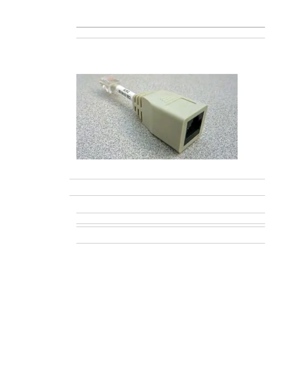
• Connect the RJ45F to RJ45M rolled serial adapter to the console port if you are connecting the
system to a serial console server with a standard CA
T5 cable, and then connect the CAT5 cable to
the adapter. The adapter provides the appropriate pinout connection to your equipment. For
information about cable and connector pinout specifications, see F5 Platforms: Accessories at
support.f5.com/kb/en-us/products/big-ip_ltm/manuals/product/f5-plat-
accessories.html.
Figure 7: The RJ45F to RJ45M rolled serial (pass-through) adapter (CBL-0143-00)
3. Connect power to installed power supplies:
Note: Be sur
e to route the power cords away from the fan tray so that the cords do not impede access
to it.
• For AC-powered systems, connect an auto locking power cable to the power input panel on all
installed power supplies, and then connect the cable to the power source.
Note
: Not all country-specific power cables include a locking feature.
Note: T
o remove the locking power cord, pull one or both of the power cord locking tabs away
from the power supply.
• For DC-powered systems, connect a DC cable to each power supply and then connect the cable to
your DC mains power source.
4. If you plan to set up device service clustering (
DSC
®
) with hard-wired failover capacity, connect the
serial failover cable to the FAILOVER port on each unit.
For more information about configuring failover, see BIG-IP
®
Device Service Clustering:
Administration at support.f5.com.
You can now assign a management IP address to the system, and then license and provision the software.
Optionally, you should run the QKView utility. This utility collects configuration and diagnostic
information about your system into a single file that you can provide to F5 Technical Support to aid in
troubleshooting. For more information, see support.f5.com/csp/article/K12878.
Platform Installation
28