July, 2006
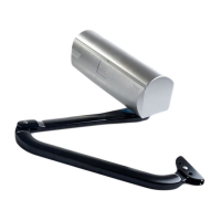
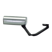
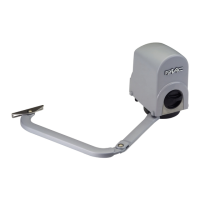
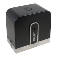
390 24v Operator And
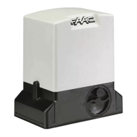
425 D Control Panel
Installation Manual
CONTENTS
T HE 390 24V OPERATOR AND
425 D C
ONTROL PANEL:
I
NSTALLATION MANUAL
FAAC International, Inc.
303 Lexington Avenue
Cheyenne, WY 82007
www.faacusa.com
Important Safety Information 2
Technical Data 4
Unpacking the Operator 5
The 390 24V Operator General Characteristics 6
Installation Instructions 6
Prepare the Gate 6
Manual Release Mechanism 6
Install the Operator 7
Mounting Dimensions 7
Mounting the Base Plate 7
390 Limit Switch Instructions 10
Exploded View, 390 24V Operator 12
390 24V Operator Parts List 13
The 425 D Control Panel General Description 14
Installing the 425 D Control Panel 14
Connect the Main Power Supply 14
Connect the Operator to the Control Panel 14
Connect Accessory Devices 15
Set Operating Modes 16
Setting the DIP Switches 17
Obstacle Recognition 17
Programming 19
Display Descriptions 20
Programming the Motor Run Time 20
Fuse Ratings 20
Maintenance 21
Safety in Gate Design 21
Troubleshooting 22
Limited Warranty 24
The 425 D Control Panel
Installation Instructions