8
ENGLISH
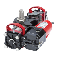
1 Gearmotor 391 E
2 Gearmotor 391*
3 Flashing lamp
4 Key-operated selector switch
5 Photocell transmitter
6 Photocell receiver
7 Electric lock **
* (only for two leaf applications)
** (obligatory for leaf L>2m)
4. ELECTRICAL CONNECTIONS
• The lay-out below refers to an installation with two motors,
with all safety and signalling devices connected.
• For two-motor applications, use a cable, type H05RN-F
to connect the MASTER and SLAVE operators.
5. INSTALLATION
5.1. PRELIMINARY CHECKS
To ensure a correctly operating automated system, the structure of
the gate to be moved must satisfy the following requirements:
• The mechanical construction elements must comply with the
provisions of the EN12604 and EN 12605 standards.
• leaf length must conform to the operator characteristics (see
paragraph 2)
• sturdy, rigid gate structure, suitable for the automated system
• smooth, uniform gate movement, without any friction and
jamming during the entire opening;
• adequately sturdy hinges, in good condition
• an efficient earth socket for connection of the operator
We advise you to carry out the metalwork jobs if any,
before installing the automated system.
• The condition of the gate structure directly influences the
reliability and safety of the automated system.
• If the leaf to be motorised incorporates a door for the
pedestrian passage it is compulsory to add a safety
switch on the door, connected to the stop input, in order
to inhibit the operation of the automated system when
the door is open.
• The gearmotor cannot be used to move safety exits or
gates fitted on emergency routes (escape routes).
5.2 INSTALLATION DIMENSIONS
Procedure for finding the securing position of the operator, using
Fig.4 to help you:
• measure dimension “A” of the gate and trace a horizontal
line on the graph on the measured value, this line to cross the
whole graph.
• you will obtain the maximum permissible angular opening
according to dimension “A” of the graph.
• select the opening range you require
• select dimension “B” so that it intersects the horizontal line
(dimension “A”) inside the required opening range.
• If dimension “A” permits opening values greater than
the opening value selected, the value of dimension “B”
can change up to the maximum permissible opening
value.
• Make sure that the minimum dimension of 450mm in
Fig.4 is observed.
• When the operator has been installed, check if dimension
“X” in Fig.4 is minimum 500 mm. If dimension “X” is less
than 500mm, run an impact test on the point indicated
in Fig.4, as described in UNI EN12445 standard, and
make sure that the measured values conform to the
specifications of UNI EN 12453 standard.
• If the thrust values are not within the values specified in
UNI EN12453 standard, the zone indicated in figure 4
MUST be protected with a protective device conforming
to the UNI EN12978 standard.
• The operator was studied and made to be secured
vertically (Fig.5). The operator cannot be installed in
other positions.
5.3. INSTALLING THE OPERATOR
When you have established dimensions “A” and “B”, you can install
the operator as follows:
Loosen by about 1/2 turn the four securing screws of the upper
housing (Fig.6 ref.) and withdraw the housing. Set the operator
for manual operation, see paragraph 7.
FIG. 4
F
IG. 5
F
IG. 6
F
IG. 3